voltage divider between the effective plate resistance and the load resistance
The plate load resistor forms a voltage divider against the Rp of the tube, in parallel with the input impedance of the next stage, which may not be uniform across the entire audio band, or the frequency of the mains and its harmonics.
When the plate load resistor is replaced with a CCS, it's effective AC impedance is in the range of 1 to 10 MEGOHMS. The PSRR is often in the range of 40 to 70 db, certainly not 6.
Measurements on the prototype SSE board which uses a 10M45 CCS chip between raw B+ and the plate of a 12AT7 triode using an intentionally polluted power supply revealed measurements in the 60db range. These measurements were probably a bit worse that the competed amp actually makes due to the lack of a chassis or optimum grounding.
Some have stated that a simple amp with few components in the signal path yet ample power output might be their definition of blameless. How about a SE amp with 14 components in the amp, not counting the power supply? What if it was flat from 8 Hz to 60 KHz, with a full power saturation limit at 35 Hz? How much power would you need from this simple single ended amp to avoid clipping into ANY speaker? Is 200 WPC enough. Look at MAGZ ultimate "cost is no object" amplifier. Who can find blame here.....even if it does have a mosfet follower in the signal path. Can you find another way to build this without a mosfet?
Schematic is in the first post
http://www.diyaudio.com/forums/tubes-valves/232484-midlife-crisis-my-833c-amp-build.html
Keit,
I have not been able to find any information on [Murray topology].
Steven
The link supplied by the TheGimp gives a quite good discussion on it, but the date is given incorrectly.
Murray's original paper is in two parts:-
Design considerations and measuring equipment for low distortion amplifiers; C T Murray, Proceedings of the Institution of Radio Engineers Australia, Vol 21 No 3 March 1960, pages 129-133
and
A low distortion single-ended push-pull audio amplifier; C T Murray, Proceedings of the Institution of Radio Engineers Australia, Vol 21 No 3 March 1960, pages 134-137
I recall it has been mentioned a few times in threads on this forum. Some members of diyAudio had problems with it, but happens, Murrays' concept is very good and is a form of the Sandman feedforward arrangement as TheGimp's link points out.
How about a SE amp with 14 components in the amp, not counting the power supply? What if it was flat from 8 Hz to 60 KHz, with a full power saturation limit at 35 Hz? How much power would you need from this simple single ended amp to avoid clipping into ANY speaker? Is 200 WPC enough. Look at MAGZ ultimate "cost is no object" amplifier. Who can find blame here.....even if it does have a mosfet follower in the signal path. Can you find another way to build this without a mosfet?
http://www.diyaudio.com/forums/tubes-valves/232484-midlife-crisis-my-833c-amp-build.html
hey! if your cat is playing around, following some fly or bug, and incidentally jumps over the rack, touching the 833 anode, well, you'll need to switch off the amp, and clean out some rests from the tube glass. Other than that, it seems to me truly blameless.
Just wisely solid state assist the Mullard, the Williamson, the Quad and a "power driven" SE ?
I want to ask, for my education, why an UL output will be any better than an optimally worked pure penthode/tetrode?
Due to internal phyics, triode distortion is almost all 2nd harmonic, there is only very small 2nd harmonic generated. Tetrodes and pentodes are more efficient and generate more power, and they have more gain, so you have have greater neg feedback. But they generate a fair bit of 3rd harmonic as well as 2nd.
In a transformer output push-pull stage operating in Class A, even order harmonics are cancelled out in the transformer. This is because the phase of even order harmonics is the same regardless of whether the phase of the signal is inverted (as in the phase splitter) or not.
So, a Class A push pull amplifier has (subject to tube matching) zero even order distortion. Only odd order distortion.
The UL connection is essentially a form of negative feedback into the screens. It turns out that by using a sweat spot in the turns ratio, the third harmonic is reduced to triode levels while retaining very nearly the power output of tetrodes or pentodes. Indoing this each tube generates more second harmonic, but that doesn't matter because its canceled out in the transformer.
Furtther, the local feedback of UL cleans up the frequency/pahse performnce of the output stage, allowing greater global feedback.
As the screen/plate gm is curved, you can aslao tweak the resistance usually placed in series with the screens. The main purpose of this resistors is to prevent parasitic oscillation, but there is a sweet spot value where distortion is further reduced.
Last edited:
Thanks! the problem then, is how to found the "sweet spot" for the particular tube you want/need to use..
Thanks! the problem then, is how to found the "sweet spot" for the particular tube you want/need to use..
Not at all difficult. The tranformer tapping sweat spot is very broad and for audio power tetrodes is usually around the 40 to 45% tapping point.
For pentodes, the optimal tapping can be lower. Also, many commercial UL designs have the tapping at around the 20 to 25% level. This being a lower amount of negative feedback there is less risk of instability, so a cheaper transformer can be used. Distortion is not significantly worse.
The improvement with tweaking the screen resistors is only small and not in the least critical.
take a look
those are too big to link directly:
https://drive.google.com/file/d/0BzwiAWo-V4C-cFliVDgxMmtKeUk/view?usp=sharing
https://drive.google.com/file/d/0BzwiAWo-V4C-WU9vdnhMUGppWTg/view?usp=sharing
those are too big to link directly:
https://drive.google.com/file/d/0BzwiAWo-V4C-cFliVDgxMmtKeUk/view?usp=sharing
https://drive.google.com/file/d/0BzwiAWo-V4C-WU9vdnhMUGppWTg/view?usp=sharing
Attachments
The improvement with tweaking the screen resistors is only small and not in the least critical.
probably you'll like to adjust screen Rs so that, the voltage at G2 is not higher than at the plate..
@tubelab.com,
... if someone wanted vanishingly low THD he wouldn't be picking a tube amplifier to begin with.
Not necessarily. You CAN have vanishingly low THD with a tube amp. It's been done. Its just that many don't WANT low THD. In the tube era there was no incentive to get THD really low as signal sources (those 12" diameter black plastic disks) were not clean to begin with. And of course it costs more to achieve in a tube amp.
The challenge is to design a tube amplifier that performs as well as a good SS amplifier whilst retaining the amicable and magical presentation a tube amplifier offers, that's one thing a tube amplifier offers over a SS amplifier, those glowing tube are intriguing and wonderful to look at (at least in my opinion).
I very much agree.
But [a very good tube amp] that wouldn't be blameless (if for no other reason that tubes are a massively inefficient alternative to transistors). Tubes automatically carry more 'blame' than transistors. Anything you could do with tubes you could also do with transistors, but with even less blame. You can't have a 'blameless' valve amp, by definition, because they will always be 'blameful' devices compared to transistors.
Anything you can do with tubes you can most certainly do with transistors. But you can certainly really wel with tubes if you know how and put the work in.
Tubes do not inherently have built-in "blame". Its how they are used - the circuit. Tubes are not blameworthy in the respect of being less linear, and neither in the Doug Self concept of the circuit having no design faults. The term "blameless" as Self used it is equally applicable to tube amps.
Last edited:
probably you'll like to adjust screen Rs so that, the voltage at G2 is not higher than at the plate..
Don't use the screen resistors to do that. Tubes designed for audio are designed to have the same DC voltage on both screen and anode.
If you use TV line output tubes a different approach is needed. Thse tubes are designed to operate the screens from the TV B+ line, a much lower voltage than the anode supply. If you want to use TV line output tubes in UL at full power without exceeding the screen rating, feed the screens via a separate transformer winding having its centre tap connected to the appropriate voltage DC supply.
hey! if your cat is playing around
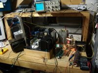
That's not my amp, but if you follow the thread to the end, you will see a very nice looking amp with vent capped Pyrex cylinders enclosing the tubes.
My 833A test amp however was so scary that I kept a 1/4 inch Lexan sheet between me and It. Look carefully at this picture. That yellow Radio Shack quality clip lead is carrying 1500 volts from the 1/2 amp power supply that is standing on edge. The plate current meter behind the tube reads 250 mA. The connections to the tube are made with Vise Grips and hose clamps. If I had a cat this thing could vaporize it.
It only existed for a week as an exercise to test the custom OPT seen to the right of the tube. The transformer failed to meet its design criteria, so the amp was never built. I still have all the parts, and may build a killer (in more ways than one) guitar amp some day.
This amp was created by taking my existing 845 SE amp, and wiring in an output tube that was 4 times bigger than the amp was designed for. Then I wired in a power supply that was rated to supply 750 watts of power. The 845SE never missed a beat, even though I plugged in my guitar preamp and attempted to blow this thing up with my guitar playing. I did manage to trip the 15 amp bench breaker twice though.
Note: This amplifier is NOT blameless, it has been blamed for several annoyed neighbors. The guitar testing could be heard from 2 blocks away. It was also the source for the picture seen in my avatar.
Construction and test details:
833 SE | Tubelab
Attachments
Don't use the screen resistors to do that. Tubes designed for audio are designed to have the same DC voltage on both screen and anode.
Not always. This doesn't apply to the 6L6-oids.
If you use TV line output tubes a different approach is needed. Thse tubes are designed to operate the screens from the TV B+ line, a much lower voltage than the anode supply. If you want to use TV line output tubes in UL at full power without exceeding the screen rating, feed the screens via a separate transformer winding having its centre tap connected to the appropriate voltage DC supply.
You can also substitute parallel NFB or cathode NFB. The TV HD types are clean enough that you could skip lNFB around the finals. Even though the spec sheets don't mention audio, these work very well as audio finals. Did a design with 6BQ6s, and these sound as good as the famous 6V6 and make over twice the power.
Given the low screen voltage, screen drive becomes practical as another form of trioding.
.... Tubes designed for audio are designed to have the same DC voltage on both screen and anode.
....
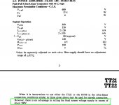
Recommended operating conditions for KT88 (tetrode mode) include a VG2 of about 300V, even when the Anode is fed from nearly 600V supply. The note, attached, from the Marconi TT21 data sheet, goes so far as to indicate that VG2 over ~300V is futile.
The EL34 is also designed for substantially higher anode voltages, compared to VG2, if the designer requires it.
Attachments
The plate load resistor forms a voltage divider against the Rp of the tube, in parallel with the input impedance of the next stage, which may not be uniform across the entire audio band, or the frequency of the mains and its harmonics.
When the plate load resistor is replaced with a CCS, it's effective AC impedance is in the range of 1 to 10 MEGOHMS. The PSRR is often in the range of 40 to 70 db, certainly not 6.
Yes very true. The CCS is another excellent way to avoid PSRR.
I think I was reading about an SRPP - but when it's loaded of course that changes in level.
I guess the PSRR problem really occurs if/when the impedance ratio changes due to signal 'height' (instantaneous level), thus changing the amount of PSRR depending upon where (between 0 and +V) the signal happens to be. Not an issue with a decent CCS as that ratio should remain fixed due to the infinite term of the CCS!
You don't see them SY - this isn't television, you hear them!!SY said:Do you have data showing these "echoes" which no one else has ever seen?
Even if GNFB amplifier is stable what do you think happens to that signal you feed back in? Of course it goes round and round - there is literally no where else for it to go unless you build an identical error amplifier and sum the outputs. Feedback literally means feeding back in, it's not called a loop for nothing. With a stable amp that signal gets smaller each time around but it's still there and you'll therefore still hear it. After a few times around it will have passed the phase margin too and may no longer be getting smaller.
Lynn Olson has some interesting comments on this: The Sound of the Machine
Olson said:he Effects of Feedback on Harmonic Structure
The Williamson amplifier of 1947 was the design that did the most to popularise the "feedback cures all ills" philosophy. It is interesting during the period from 1948 to 1956, almost all commercial hi-fi amplifiers were Williamson topologies (with minor exceptions for Quad II, McIntosh, and EV Circlotron). During this formative period the mantra of "more power, lower THD" became the driving force in the industry. By 1960, ultra-wide bandwidth, heavy feedback, and Class AB EL34 and 6550 UL circuits ruled the industry.
In the span of twelve years, the traditional audio-engineering prejudice against high-distortion devices faded, opening the door to high-power pentodes and Class AB operation. Each "improvement" was characterized by an increase in device distortion, which was then "corrected" by more and more feedback. Transistors circuits with even higher feedback ratios were the next obvious step - after all, they had more power, lower THD, more bandwidth, and most important of all, cost less to build.
Norman Crowhurst wrote a fascinating analysis of feedback multiplying the order of harmonics, which has been reprinted in "Glass Audio," Vol 7-6, pp. 20 through 30. He starts with one tube generating only 2nd harmonic, adds a second tube in series (resulting in 2nd, 3rd, and 4th), and then makes the whole thing push-pull (resulting in 3rd, 5th, 7th, and 9th), and last but not least, adds feedback to the circuit, which creates a series of harmonics out to the 81st. All of this complexity from "ideal" tubes that only create 2nd harmonic!
With real devices there are even more harmonics. In terms of IM, actual amplifiers have complex and dynamic noise floors thanks to the hundreds of sum-and-difference IM terms. That's not even counting the effects of reactive loads, which adds a frequency dependency to the harmonic structure! (With reactive loads, additional harmonics appear due to the elliptical loadline seen by the power tubes. The elliptical load-line dips into the very nonlinear low-current region, resulting in an instantaneous increase in upper harmonics. This spectral "roughening" is most audible with strong low frequency program material and hard-to-drive horn or vented bass drivers.)
As Crowhurst noted, feedback mostly reduces the 2nd and 3rd harmonics, leaving the upper ones more or less alone, or sometimes even greater than before. Feedback fools the simple THD meter, but the spectrum analyzer sees through the shell game. Too bad raw power and almost useless THD measurements became the end-all and be-all for more than 50 years. If more engineers and reviewers had access to spectrum analyzers, the misleading nature of raw THD measurements would have been discovered earlier, and amplifier design might have taken a different course.
As I said, I only want to listen to my OPT once!!
As I said, I only want to listen to my OPT once!!
You listen to it less than once if it's inside a feedback loop.
You don't see them SY - this isn't television, you hear them!!
If there's echoes, they'll show up on a scope. I've never seen them and I find no mention in the literature of them. If they existed, all of modern control theory is incorrect.
This is a stunningly remarkable claim. Do you have any actual evidence that they exist?
Even if GNFB amplifier is stable what do you think happens to that signal you feed back in? Of course it goes round and round - there is literally no where else for it to go unless you build an identical error amplifier and sum the outputs. Feedback literally means feeding back in, it's not called a loop for nothing. With a stable amp that signal gets smaller each time around but it's still there and you'll therefore still hear it. After a few times around it will have passed the phase margin too and may no longer be getting smaller.
Ohhh noooo - not again!
jan
I'm with Jan on this one, if someone lacks understanding of control loop theory it makes sense he thinks feedback is a process where signals get fed back to the input and goes around a few times. It rather painfully illustrates that the person in question needs to spend a few evenings reading up on control loop theory.
Can we please keep this discussion based on proven theory and science please, there's enough quackery in the audio industry already.
Thanks for your consideration!
Can we please keep this discussion based on proven theory and science please, there's enough quackery in the audio industry already.
Thanks for your consideration!
Even if GNFB amplifier is stable what do you think happens to that signal you feed back in? Of course it goes round and round -
This is a nonsense, feedback circuit compares instant input with divided output to make an error voltage. There is a frequency dependent phase shift between input and output, so the proper frequency compensation is to be made in order to fulfill stability criterion.
- Status
- Not open for further replies.
- Home
- Member Areas
- The Lounge
- "blameless" standard for tube amplifiers?