Hello AndrewT,
I thought about it, re-read the chapter, and understood. You're right man: however the precise value for the resistor is difficult to find, 10ohm makes undercompensation, and 12ohm make the Vbemult overcompensated with respect to rail voltage, but we're talking about a mA or two in the output transistors, when the rails move in a 15% range.
Thank you very much
Updated schematic:
AndrewT said:R55 is in the wrong location.
It should be in the horizontal feed to the top of the multipliying transistor, not in the vertical feed to the resistor divider string.
I thought about it, re-read the chapter, and understood. You're right man: however the precise value for the resistor is difficult to find, 10ohm makes undercompensation, and 12ohm make the Vbemult overcompensated with respect to rail voltage, but we're talking about a mA or two in the output transistors, when the rails move in a 15% range.
Thank you very much
Updated schematic:
Attachments
RE Giaime's schematic
In a previouys post, I made comments about this proposed amplifier. My previous remarks were in part , based around the supplied schematic that mainly covered the input stage.
The following are personal opinions , based around experience of front end supply decoupling and several more obvious areas.
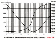
1. No fusesare shown 2. There are no onboard decoupling capacitors adjacent to the output stage. 3.The use of the simple 1,000uF/220R network will result in a far less than neutral sound due to resonance and phase effects of the 1,000uF capacitor over the audible bandwidth. (SEE Attachment) Under large, low frequency output conditins, the 220R resistor may prevent rapid recovery of the full front end supply voltage. Perhaps a smaller value resistor with a series diode would have been better?
I think Douglas Self's method of no resistor in the +VE rail feed to the front end, combined with his usual filtering method for the current source is a better approach. Carlos has recently demonstrated in his own thread, that a capacitance multiplier with a limiting zener diode supplying the front end gives audibly better results, Even better results, particularly with low level HF detail ,will be obtained with a low noise, VERY low impedance supply for the front end.(Even after using normal voltage regulation.) 4. I am concerned that the loaded side of the current mirror will only have approx. 600mV from collector to -VE rail.
Perhaps reducing the vast amount of available gain in the VAS by fitting an emitter resistor, will not only help with stability, which may be marginal in a real amplifier, but would also permit the removal of the awkward 88.5R resistor (R77)
5. R27 in the input filter appears to be unduly high a value. The lower HF rolloff point will result in some loss of higher order harmonic information, which is necessary for the best soundstage and separation between instruments and voices.
There are a few other areas that worry me a little, but I will let other forum members make any further comments.
Giaime, these are suggestions based on many years of personal exoerience, and are offered as constructive criticism.
BTW, there are several other Sydney DiyAudio members who can verify the desireability of the improvements to the front end power supply .
Regards
SandyK
In a previouys post, I made comments about this proposed amplifier. My previous remarks were in part , based around the supplied schematic that mainly covered the input stage.
The following are personal opinions , based around experience of front end supply decoupling and several more obvious areas.
1. No fusesare shown 2. There are no onboard decoupling capacitors adjacent to the output stage. 3.The use of the simple 1,000uF/220R network will result in a far less than neutral sound due to resonance and phase effects of the 1,000uF capacitor over the audible bandwidth. (SEE Attachment) Under large, low frequency output conditins, the 220R resistor may prevent rapid recovery of the full front end supply voltage. Perhaps a smaller value resistor with a series diode would have been better?
I think Douglas Self's method of no resistor in the +VE rail feed to the front end, combined with his usual filtering method for the current source is a better approach. Carlos has recently demonstrated in his own thread, that a capacitance multiplier with a limiting zener diode supplying the front end gives audibly better results, Even better results, particularly with low level HF detail ,will be obtained with a low noise, VERY low impedance supply for the front end.(Even after using normal voltage regulation.) 4. I am concerned that the loaded side of the current mirror will only have approx. 600mV from collector to -VE rail.
Perhaps reducing the vast amount of available gain in the VAS by fitting an emitter resistor, will not only help with stability, which may be marginal in a real amplifier, but would also permit the removal of the awkward 88.5R resistor (R77)
5. R27 in the input filter appears to be unduly high a value. The lower HF rolloff point will result in some loss of higher order harmonic information, which is necessary for the best soundstage and separation between instruments and voices.
There are a few other areas that worry me a little, but I will let other forum members make any further comments.
Giaime, these are suggestions based on many years of personal exoerience, and are offered as constructive criticism.
BTW, there are several other Sydney DiyAudio members who can verify the desireability of the improvements to the front end power supply .
Regards
SandyK
Attachments
Giaime said:I thought about it, re-read the chapter, and understood.
Hi Giaime,
I was hoping my subtle suggestion would have been enough. I had compared your schematic to Douglas Self's before I posted. I just don't like telling someone they are wrong.
regards
Re: RE Giaime's schematic
Hello friends!
You're absolutely welcome!
This was never intended as a "final" schematic. Nor I proposed someone to build it: maybe I should have warned better, writing "non definitive" on the schematic, or "don't build this" maybe. This is only in developing process, in SPICE, where details such as fuses and output stage decoupling are absolutely non necessary.
I'm precisely working on this. I think I will probably use the same type of circuit, a gyrator.
I'm also working on this. I think that the gain reduction will be marginal: an emitter resistor in that position has a limited effect, since the VAS is converting a current to voltage. Its current is almost fixed, so no signal can develop on the emitter resistor. However since this isn't a perfect word, and the diffamp hasn't infinite output resistance and the VAS hasn't perfect CCS loading, the gain will be reduced and maybe we can omit the 88.5R resistor (a trimmer, of course) to balance the Vce of the diffamp's bjts.
However I checked, and an emitter resistor in the VAS will degrade stability, with this design in this situation (that's not a rule, I mean).
You made a good point
Mah. The input network has less than -0.75dB loss at 50kHz: of course 2k2 is a value to be considered with zero output impedance preamplifiers: in real world I would reduce this to avoid the low pass filter corner frequency, in combination with the preamp output impedance, to come to play in the audio band. With the same values I think I could reduce it to 1k.
I'm very grateful of your experienced suggestions. This is a forum, to exchange experiences, and help novices like me Nobody should take it personally or blame someone for discovering faults in the designs.
I just write about the beauty of being part of a technical forum like this. And here you come: are you talking to me? Do we already meet before?
Ehehehe, great Greg, thank you very much. I had doubt, you see, for that circuit, because some time ago there was a thread here on the various configurations of D.Self's Vbe multipliers, and there were doubts on what was the correct configuration. I tried in the simulation and understood what was the better one
Hello friends!
sandyK said:In a previouys post, I made comments about this proposed amplifier. My previous remarks were in part , based around the supplied schematic that mainly covered the input stage.
The following are personal opinions , based around experience of front end supply decoupling and several more obvious areas.
You're absolutely welcome!
1. No fusesare shown 2. There are no onboard decoupling capacitors adjacent to the output stage.
This was never intended as a "final" schematic. Nor I proposed someone to build it: maybe I should have warned better, writing "non definitive" on the schematic, or "don't build this" maybe. This is only in developing process, in SPICE, where details such as fuses and output stage decoupling are absolutely non necessary.
3.The use of the simple 1,000uF/220R network will result in a far less than neutral sound due to resonance and phase effects of the 1,000uF capacitor over the audible bandwidth. (SEE Attachment) Under large, low frequency output conditins, the 220R resistor may prevent rapid recovery of the full front end supply voltage. Perhaps a smaller value resistor with a series diode would have been better?
I think Douglas Self's method of no resistor in the +VE rail feed to the front end, combined with his usual filtering method for the current source is a better approach. Carlos has recently demonstrated in his own thread, that a capacitance multiplier with a limiting zener diode supplying the front end gives audibly better results, Even better results, particularly with low level HF detail ,will be obtained with a low noise, VERY low impedance supply for the front end.(Even after using normal voltage regulation.)
I'm precisely working on this. I think I will probably use the same type of circuit, a gyrator.
4. I am concerned that the loaded side of the current mirror will only have approx. 600mV from collector to -VE rail.
Perhaps reducing the vast amount of available gain in the VAS by fitting an emitter resistor, will not only help with stability, which may be marginal in a real amplifier, but would also permit the removal of the awkward 88.5R resistor (R77)
I'm also working on this. I think that the gain reduction will be marginal: an emitter resistor in that position has a limited effect, since the VAS is converting a current to voltage. Its current is almost fixed, so no signal can develop on the emitter resistor. However since this isn't a perfect word, and the diffamp hasn't infinite output resistance and the VAS hasn't perfect CCS loading, the gain will be reduced and maybe we can omit the 88.5R resistor (a trimmer, of course) to balance the Vce of the diffamp's bjts.
However I checked, and an emitter resistor in the VAS will degrade stability, with this design in this situation (that's not a rule, I mean).
You made a good point
5. R27 in the input filter appears to be unduly high a value. The lower HF rolloff point will result in some loss of higher order harmonic information, which is necessary for the best soundstage and separation between instruments and voices.
Mah. The input network has less than -0.75dB loss at 50kHz: of course 2k2 is a value to be considered with zero output impedance preamplifiers: in real world I would reduce this to avoid the low pass filter corner frequency, in combination with the preamp output impedance, to come to play in the audio band. With the same values I think I could reduce it to 1k.
There are a few other areas that worry me a little, but I will let other forum members make any further comments.
Giaime, these are suggestions based on many years of personal exoerience, and are offered as constructive criticism.
BTW, there are several other Sydney DiyAudio members who can verify the desireability of the improvements to the front end power supply .
Regards
SandyK
I'm very grateful of your experienced suggestions. This is a forum, to exchange experiences, and help novices like me
Nobody should take it personally or blame someone for discovering faults in the designs.gmphadte said:Don't post anything correct after his thread. He will neither check nor correct his mistake. Instead he will dislike the poster.
Gajanan Phadte
I just write about the beauty of being part of a technical forum like this. And here you come: are you talking to me? Do we already meet before?
Greg Erskine said:Hi Giaime,
I was hoping my subtle suggestion would have been enough. I had compared your schematic to Douglas Self's before I posted. I just don't like telling someone they are wrong.
regards
Ehehehe, great Greg, thank you very much. I had doubt, you see, for that circuit, because some time ago there was a thread here on the various configurations of D.Self's Vbe multipliers, and there were doubts on what was the correct configuration. I tried in the simulation and understood what was the better one
Re: Giaime's schematic
Hello SandyK,
yes, I understood. I'm trying to do this: it seems that 43ohm is the right value to balance the Vce of the diffamp transistors.
I thought a little about this, and read a part of Carlos' thread on his amplifier, particulary the contributions by Maynard.
How would you see an "heavy modification" of this amp, involving output stage outside global feedback loop?
This way,
- I can remove the output network. I heard it sounds better due to constant output impedance in the audio band;
- I can gain stability margin in the amplifier.
This because I fear I will have to choose between overcompensation and oversimplification, in the testing phase of the amplifier: it just doesn't seem to have much stability margin.
Of course THD will increase brutally: what do you think about this tradeoff?
Surely it isn't a "Blameless Style" amp no more
Hello SandyK,
sandyK said:Giaime
Just to make sure that we are on the same wavelrngth,in part 4. I was referring to fitting a small emitter resistur to Q29, the BC547;as this is the transistor loading the current mirror.
Regards
SandyK
yes, I understood. I'm trying to do this: it seems that 43ohm is the right value to balance the Vce of the diffamp transistors.
I thought a little about this, and read a part of Carlos' thread on his amplifier, particulary the contributions by Maynard.
How would you see an "heavy modification" of this amp, involving output stage outside global feedback loop?
This way,
- I can remove the output network. I heard it sounds better
due to constant output impedance in the audio band;- I can gain stability margin in the amplifier.
This because I fear I will have to choose between overcompensation and oversimplification, in the testing phase of the amplifier: it just doesn't seem to have much stability margin.
Of course THD will increase brutally: what do you think about this tradeoff?
Surely it isn't a "Blameless Style" amp no more
Giaime's schematic
SandyK
Giaime
As far as I am concerned, the Zobel networks are there for very good reasons. The most I ever do in that area is perhaps reduce the inductance slightly by using a heavier guage wire, and reduce the typical 150nF capacitor to 100nF. Without the Zobel, there may be a problem driving capacitive loads.
It is still possible to get truly excellent distortion figures with a Zobel in circuit.
SandyK
I will send you an email
SandyK
Giaime
As far as I am concerned, the Zobel networks are there for very good reasons. The most I ever do in that area is perhaps reduce the inductance slightly by using a heavier guage wire, and reduce the typical 150nF capacitor to 100nF. Without the Zobel, there may be a problem driving capacitive loads.
It is still possible to get truly excellent distortion figures with a Zobel in circuit.
SandyK
I will send you an email
Re: Giaime's schematic
Thank you very much Alex for your reply. I must say I was never to remove the Zobel network: I would like to eliminate the output inductor. Maybe taking a greater care with capacitive cables, do you think it's doable and do you see advantages?
I would like Maynard opinion on this: I read about this in one of his posts.
sandyK said:SandyK
Giaime
As far as I am concerned, the Zobel networks are there for very good reasons. The most I ever do in that area is perhaps reduce the inductance slightly by using a heavier guage wire, and reduce the typical 150nF capacitor to 100nF. Without the Zobel, there may be a problem driving capacitive loads.
It is still possible to get truly excellent distortion figures with a Zobel in circuit.
SandyK
I will send you an email
Thank you very much Alex for your reply. I must say I was never to remove the Zobel network: I would like to eliminate the output inductor. Maybe taking a greater care with capacitive cables, do you think it's doable and do you see advantages?
I would like Maynard opinion on this: I read about this in one of his posts.
Graham, for sure will suggest you to remove the output coil
The coil was re-inserting into my schematic more as result of political reasons than technical reasons.
Having the output coil, people can use all kinds of speakers and cables....more safe.....of course we pay for that coil inserted there..some small loss (audible) of quality.
Also i perceived interesting as removed overshot i had into 10 kilohertz square wave form.... and this was over resistive load...try to imagine the mess with real loads having also people using long length of audio cables....one more exotic than the other.
Coil is there for safety reasons...in my own home.... it is bypassed.
regards,
Carlos
Giaime's schematic
Giaime
Personally, I wouldn't run the risk of a burnup. Don't forget though. that you can tweak the values to suit your speaker impedance, and also optimise with a square wave signal using a CRO. I haven't bothered doing that though,or researched that aspect.As you probably realise, Graham Maynard has probably forgotten more about electronics than most people know. I used to read his articles in the English electronics magazines many years ago,so Graham is the person to ask.
SandyK.
Thank you Alex, I'm very intrigued to hear it that I think I'll start a PCB design for it.
Sorry for the lack of description of the previous schematics: the two "supplies" (you see the frontend is powered by a separated Vdc) is to remember that I will divide the supplies, to get a regulated, clean one for the input stage but without losing output voltage capabilities.
Maybe I'll use a separate winding on the transformer, or maybe I'll do a la Pass, using a voltage doubler on the same windings to power a low current regulated PSU.
I'm open to suggestions for the choice of the transistors. 2SC and 2SA stuff is already ok (I will use newer version for the out of production 3281/1302), MPSA18 is from a suggestion in this topic (thanks!), others are open to choice. What would you use? I don't know very well japanese transistors, so if there is a high voltage high gain good to-92 transistor, to replace the various BC546B-556B (that has a little low beta)...
Thanks in advance
Giaime's schematic
Giaime
The separate windings idea works very well for the SiliconChip 100W ULD amplifier. I have heard a friend's modified ULD , and it would outperform most commercial amplifiers, perhaps with the exception of Hugh Dean's "Lifeforce" But , then again , I imagine that the results would be VERY close.
It always pays to buy extra BC546B and BC556B genuine Motorola/ON devices and select the higher HFE types for where they are loading the previous stage. Don't go too overboard with very high HFE devices, as CFP designs don't seem to need an invitation to be unstable !.The BC550C/BC560C and 2SA970 are very good low noise devices for the front end. Just make sure that voltage ratings are suitable for the circuit being used.
Regards
SandyK
then use bc546c/556c.Giaime said:so if there is a high voltage high gain good to-92 transistor, to replace the various BC546B-556B (that has a little low beta)...
http://www.diyaudio.com/forums/showthread.php?postid=896723#post896723
buy 25pair or 75pair and select from them
Bob did us all a great favour buying these for us for that group buy. He is still holding that excess stock bought to get our price down and meet the minimum order quantities.
Utmost respect
Carlos,
Two people (among many) I have very great respect for on this forum are YOU (for your amplifier opinions) and Andrew T. (for his technical expertise and helpful attitude) There is no competion. Room for both opinions and both perspectives.
Thanks both of you!
..Todd
Carlos,
Two people (among many) I have very great respect for on this forum are YOU (for your amplifier opinions) and Andrew T. (for his technical expertise and helpful attitude) There is no competion. Room for both opinions and both perspectives.
Thanks both of you!
..Todd
gmphadte said:2SC0281/2SA0302 are better but I don't know whether they can withstand the power requirement.
Gajanan Phadte
Are you sure of the bjt names? I can't find them.
Does 2SA970 have a complementary npn type? Should it be the 2SC2240?
- Status
- This old topic is closed. If you want to reopen this topic, contact a moderator using the "Report Post" button.
- Home
- Amplifiers
- Solid State
- Blameless, Dx was wrong, it is a very good amplifier