Hi guys, i'm planning to build my own speaker drivers for a 4-way open-baffle application.
The details are not so important as it is a typical open-baffle configuration like Linkwitz's and John K's, but
i'm struggling with the subwoofer's excursion since one subwoofer will be used per/baffle. the only important
thing, that it must handle around 14mm excursion as linearly as possible.
Well, i know that the best answer would be 'double the number of drivers', but have taken a look at a typical BL curve
and wasn't satisfied with the results.
Playing with FEMM for a while, checking the distortion levels was a must.
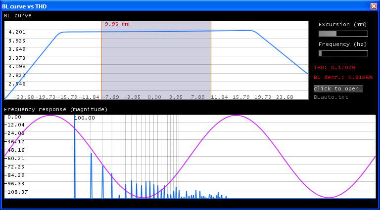
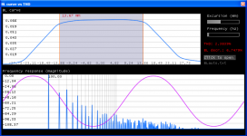
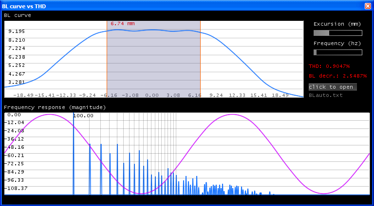
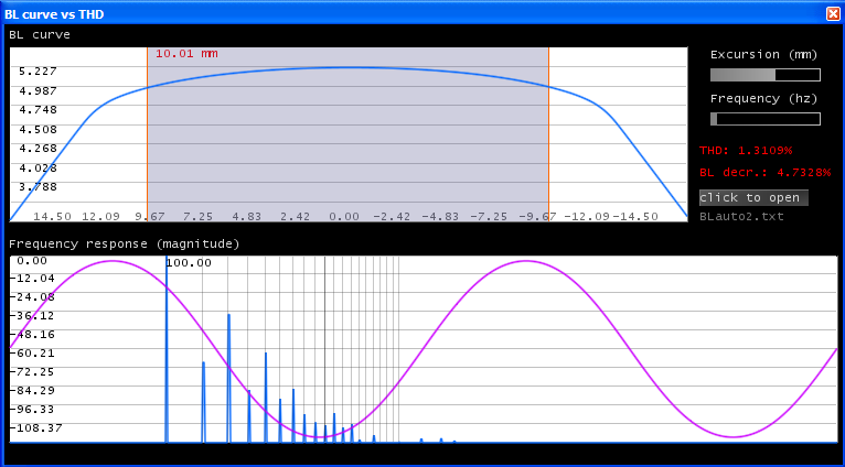
therefore i've made a simple application that evaluates the distortion and THD for a given BL curve generated by FEMM.
Let's take a look at it:
http://s5.postimage.org/jxxv44f47/app01.png
The app eats the BL curve and shapes a given wave, then the distortion is evaluated.
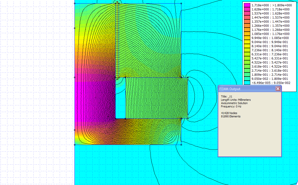
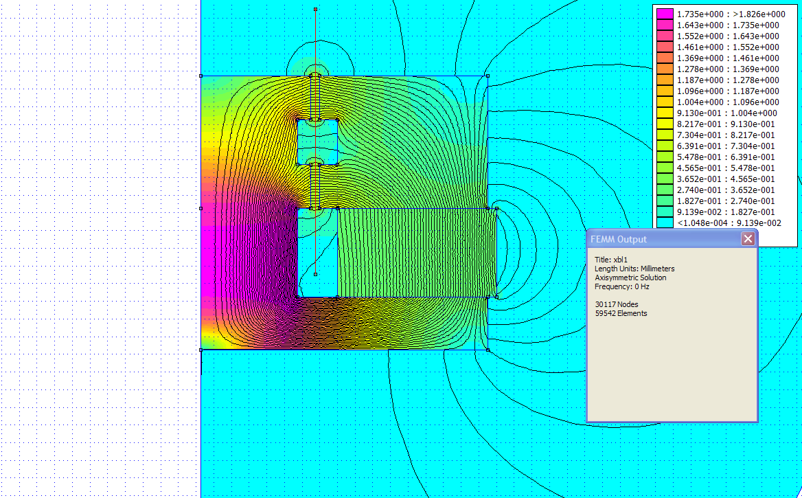
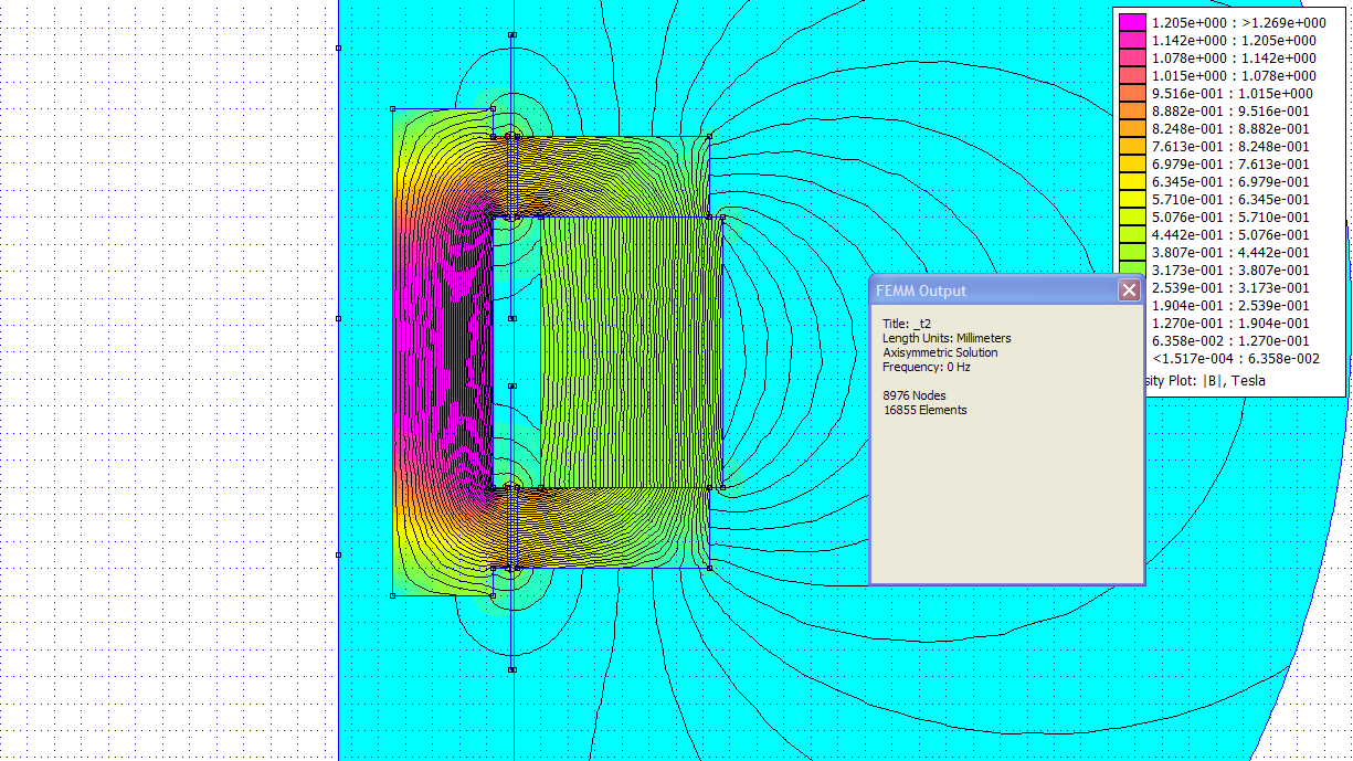
Here is (the already) optimized motor structure:
http://s5.postimage.org/vx9dbfkp3/motor01.png
Since evaluating the BL curve is a pain in the @ss, and FEMM is unable to simulate AC frequencies with permanent
magnetic fields, the BL curve is not entirely precise. I mean, shorting rings will be used, and by changing the
direction of the current in FEMM, the BL curve also changes. btw. the BL curve itself (mathematically) is an integral
of the flux density in regarding to the coil.
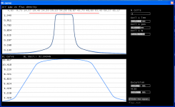
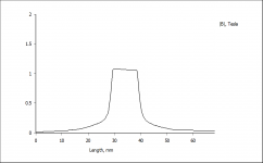
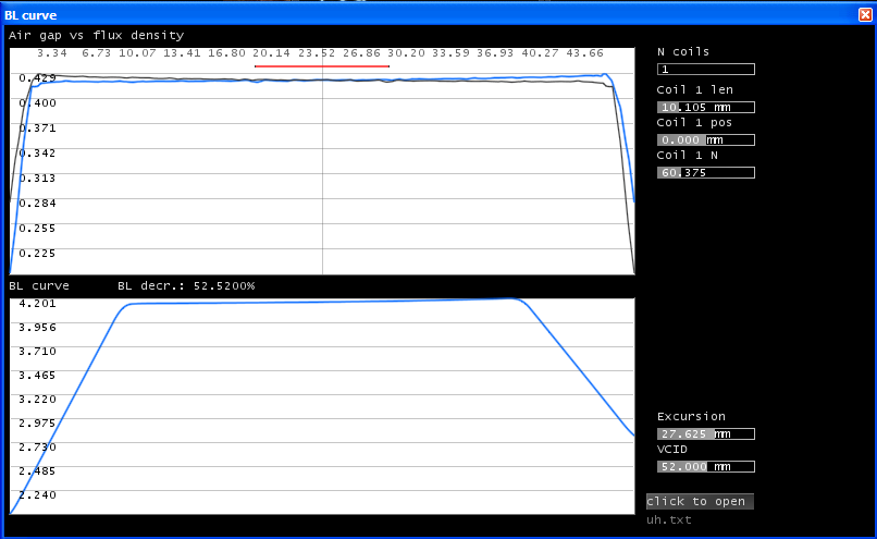
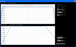
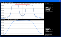
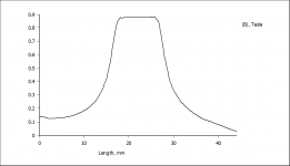
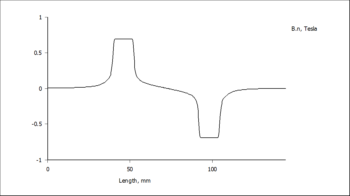
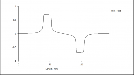
So, here is another app. that interprets the 'air gap vs flux density' curve generated by FEMM:
http://s5.postimage.org/xdkvtknlz/motor01_flux.png
http://s5.postimage.org/u9a7ws6tj/app02.png
http://s5.postimage.org/n7caal37r/app03.png
and generates the given BL curve for it. With this, basic distortion checking is simplified.
it is a simplified model, it doesn't take lorentz forces and so on into account so it is not a FEA.
there is more to this story, but i'm waiting for replies.
The details are not so important as it is a typical open-baffle configuration like Linkwitz's and John K's, but
i'm struggling with the subwoofer's excursion since one subwoofer will be used per/baffle. the only important
thing, that it must handle around 14mm excursion as linearly as possible.
Well, i know that the best answer would be 'double the number of drivers', but have taken a look at a typical BL curve
and wasn't satisfied with the results.
Playing with FEMM for a while, checking the distortion levels was a must.
therefore i've made a simple application that evaluates the distortion and THD for a given BL curve generated by FEMM.
Let's take a look at it:
http://s5.postimage.org/jxxv44f47/app01.png
The app eats the BL curve and shapes a given wave, then the distortion is evaluated.
Here is (the already) optimized motor structure:
http://s5.postimage.org/vx9dbfkp3/motor01.png
Since evaluating the BL curve is a pain in the @ss, and FEMM is unable to simulate AC frequencies with permanent
magnetic fields, the BL curve is not entirely precise. I mean, shorting rings will be used, and by changing the
direction of the current in FEMM, the BL curve also changes. btw. the BL curve itself (mathematically) is an integral
of the flux density in regarding to the coil.
So, here is another app. that interprets the 'air gap vs flux density' curve generated by FEMM:
http://s5.postimage.org/xdkvtknlz/motor01_flux.png
http://s5.postimage.org/u9a7ws6tj/app02.png
http://s5.postimage.org/n7caal37r/app03.png
and generates the given BL curve for it. With this, basic distortion checking is simplified.
it is a simplified model, it doesn't take lorentz forces and so on into account so it is not a FEA.
there is more to this story, but i'm waiting for replies.
If you actually want to build speakers, I'd suggest getting a Klippel Analyzer like the manufacturers of speakers with excellent BL curves at high Xmax values use to help in the design process.Hi guys, i'm planning to build my own speaker drivers for a 4-way open-baffle application.
the only important thing, that it must handle around 14mm excursion as linearly as possible.
Well, i know that the best answer would be 'double the number of drivers', but have taken a look at a typical BL curve
and wasn't satisfied with the results.
Why do you want to build your own drivers?
The Klippel analyzer is a clever/important one.
I don't want to compete with big companies 🙂 there are a lot of good subs available, just interested in speaker building, that's all
Regards,
Akos
I don't want to compete with big companies 🙂 there are a lot of good subs available, just interested in speaker building, that's all
Regards,
Akos
Hey Art,
The OP is interested in the design side, the Klippel only reveals the end result.
Interesting and insightful stuff Akos.
I had never tried to reverse current but I have wound coils in "reverse" in FEMM.
The OP is interested in the design side, the Klippel only reveals the end result.
Interesting and insightful stuff Akos.
I had never tried to reverse current but I have wound coils in "reverse" in FEMM.
I am more interested in HOW you are planning to build your own drivers. I think your approach is interesting, as far as I can see you are trying to reliably simulate distortion/behaviour of a design before you make it, so it would be an interesting tool in adittion to a Klippel analyzer. Before/after.
I assume you will also take into consideration weight of movable parts and physical resistance.
Surface area of gap? Will you be able to adjust gap design in simulation?
Sorry if this seems trivial.
I assume you will also take into consideration weight of movable parts and physical resistance.
Surface area of gap? Will you be able to adjust gap design in simulation?
Sorry if this seems trivial.
He said he's "just interested in speaker building", if one doesn't measure end results one won't know if the design side worked as predicted.Hey Art,
The OP is interested in the design side, the Klippel only reveals the end result.
There is a lot more to building drivers than the design side.
I'm going to pass the parameters to a loudspeaker driver engineer.
Yes, drivers cannot be made at home in a nasty environment. I'm more like a designer.
http://s5.postimage.org/wgegkpc3r/wire.png
http://s5.postimage.org/573367b0n/design.png
Regards,
Akos
Yes, drivers cannot be made at home in a nasty environment. I'm more like a designer.
http://s5.postimage.org/wgegkpc3r/wire.png
http://s5.postimage.org/573367b0n/design.png
Regards,
Akos
There is a lot more to building drivers than the design side.
Well, then which subwoofers would you recommend me for low BL distortion @ hi xmax? prices around 300$.
maybe you have custom build subs. i would take a look at them then.
KaffiMann, what do you mean by reliably simulating distortion? It's not a FEA, so a simplified model won't give realistic results as it's doesn't take AC fields and so on. into account.
... What? You mean besides these?
AE Speakers Online Store
Yeah, I get the point about not being 100% realistic, but it seems like a good start 🙂
I know about AE speakers, one of my favorites 🙂 (well, I never heard them, but i'm sure in the results)
Let's take it longer.
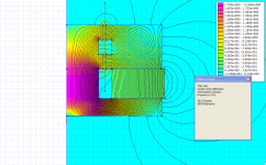
You agree that this is just a simplified model. FEMM takes the permanent field of the coil into account, but - in my opinion - it does not matter, because it also changes with the direction of the current, and if you change it to an AC waveform it can be reduced / or almost completely eliminated by a shorting ring. This is what it's called flux modulation as described by others many years before, and also influences the field of the permanent magnet itself.
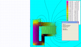
FEMM flux for DC coil zero positive & negative currents:
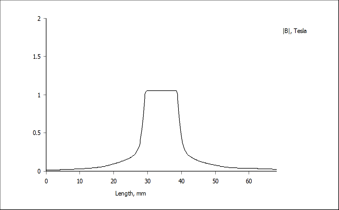
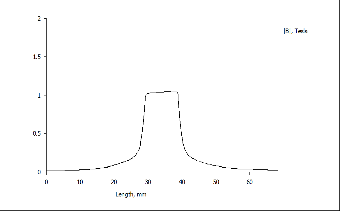
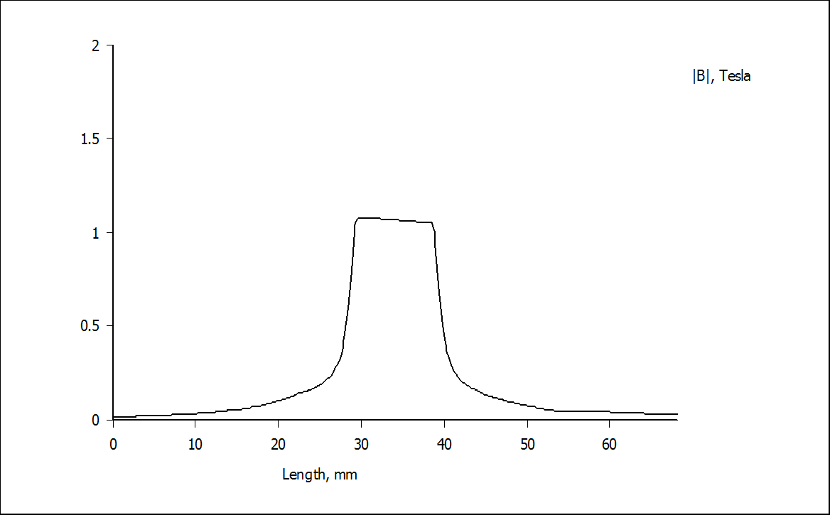
Let's ignore them now.
From our perspective, the distortion caused by other things like the spider, surround, or intermodulation distortions are irrelevant now.
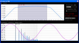
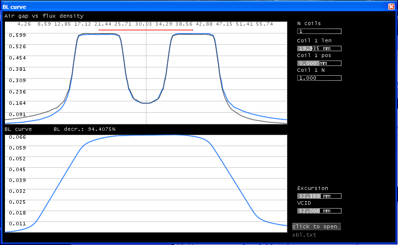
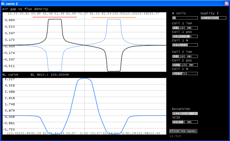
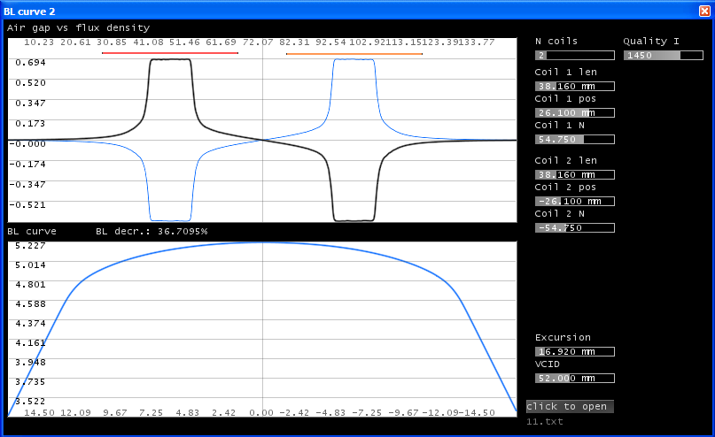
Here is the sample BL curve which is generated for the test subwoofer above for a 38mm voice coil:
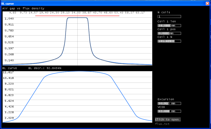
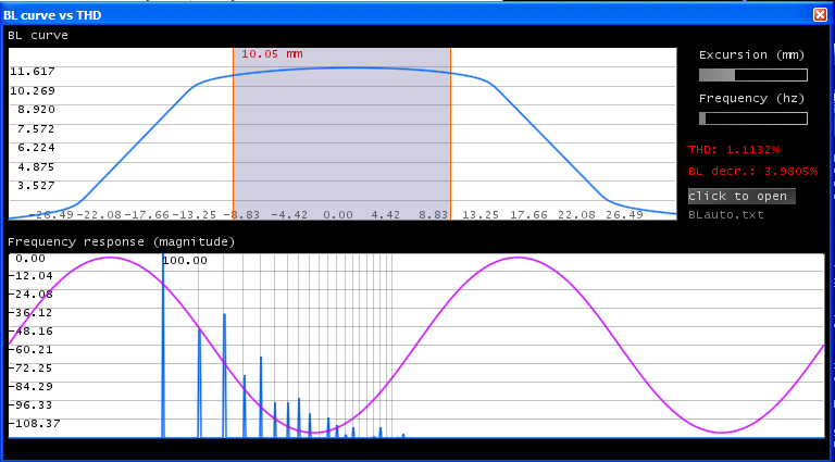
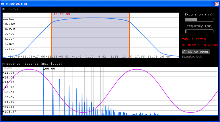
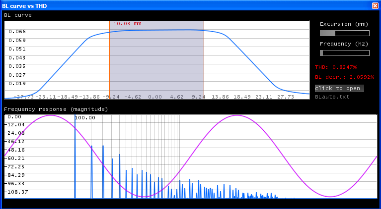
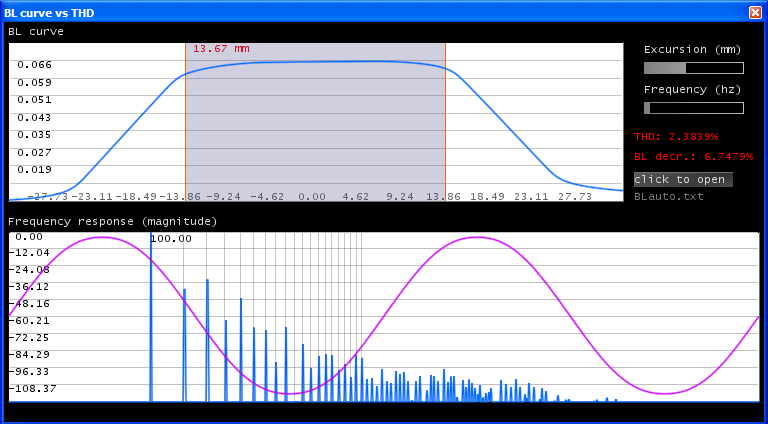
The prediction shows that it has a BL deviation of about 4% for 10mm and around 10% for 13-14mm. It follows the typical rule that BL deviation of 30% results in around 10% THD but this is an oversimplification. First the motor structure itself is somewhat optimized since it is an undercut & extended polepiece.
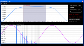
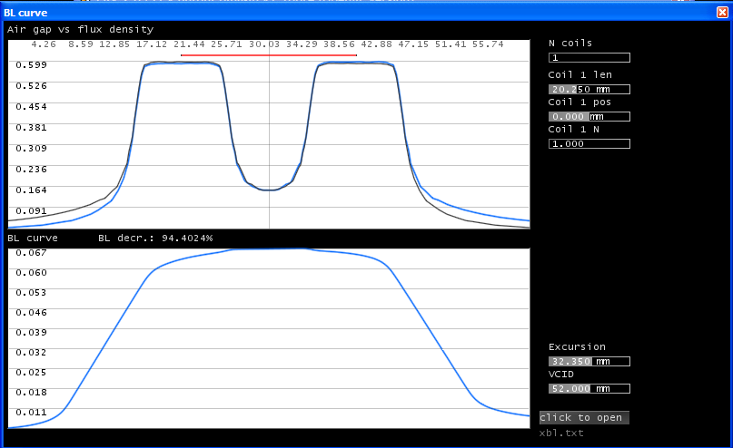
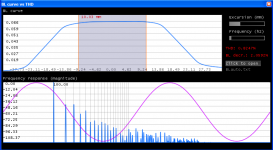
Next, I increase the length of the VC to 45mm:
The distortion figures are improved, 2nd and 3rd mainly. This is a common behaviour/solution but IMO not the best one.
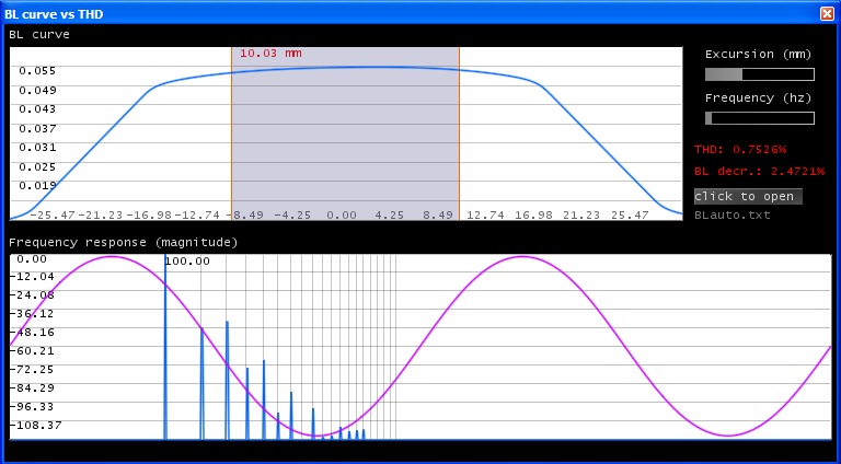

(note here that the evaluation also depends on the quality, but i wasn't able to recognize any improvement above a certain point)
...
Let's take it longer.
You agree that this is just a simplified model. FEMM takes the permanent field of the coil into account, but - in my opinion - it does not matter, because it also changes with the direction of the current, and if you change it to an AC waveform it can be reduced / or almost completely eliminated by a shorting ring. This is what it's called flux modulation as described by others many years before, and also influences the field of the permanent magnet itself.
FEMM flux for DC coil zero positive & negative currents:
Let's ignore them now.
From our perspective, the distortion caused by other things like the spider, surround, or intermodulation distortions are irrelevant now.
Here is the sample BL curve which is generated for the test subwoofer above for a 38mm voice coil:
The prediction shows that it has a BL deviation of about 4% for 10mm and around 10% for 13-14mm. It follows the typical rule that BL deviation of 30% results in around 10% THD but this is an oversimplification. First the motor structure itself is somewhat optimized since it is an undercut & extended polepiece.
Next, I increase the length of the VC to 45mm:
The distortion figures are improved, 2nd and 3rd mainly. This is a common behaviour/solution but IMO not the best one.
(note here that the evaluation also depends on the quality, but i wasn't able to recognize any improvement above a certain point)
...
Attachments
-
 motor01_flux.png8.4 KB · Views: 533
 -
 2_blcurve3 45 14mm.png43.5 KB · Views: 534
 -
 2_blcurve3 45 10mm.png42.2 KB · Views: 499
 -
 2_blcurve2 38 14mm.png47.6 KB · Views: 517
 -
 2_blcurve 38 10mm.png43.8 KB · Views: 512
 -
 2_flux 38.png41.9 KB · Views: 558
 -
 motor01_fluxneg.png8.4 KB · Views: 497
 -
 motor01_fluxpos.png8.4 KB · Views: 540
One of the best 18" in regard to low BL distortion and hi Xmax is the B&C18SW115, but it's price has gone up to more than double what you want to pay due to cost of the neodymium magnet structure.Well, then which subwoofers would you recommend me for low BL distortion @ hi xmax? prices around 300$.
maybe you have custom build subs. i would take a look at them then.
A close second is the ceramic magnet BC18TBW100 at around $349.
You can see distortion results using the B&C18SW115-4 in bass reflex and tapped horn enclosures here:
http://www.diyaudio.com/forums/subwoofers/184992-tapped-horn-vs-bass-reflex-case-study.html
I have never pursued open baffle cabinets, but I can say that a pair of B&C18SW115 run open air driven to 15 mm excursion at 20 Hz have very little distortion and enough output to make me feel ill for quite a while after only a short exposure during break in.
The suspension did loosen up a small amount (perhaps 2 mm) after several hours running around Xmax.
Art
Last edited:
Nice drivers! with good sensitivity.
(It would be great if manufacturers could share the details of copper wires, diameter etc..)
Thanks for the info.
Never used tapped horns, have to do some research before i can comment on it. Pretty backwards mounting 🙂
What kind of software is that you used there? If there are distortion measurements for pure sine waves, they are so interesting 🙂
p.s. this is the first time I saw h0 as "EtaZero" in a datasheet
I continue..
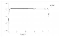
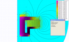
One would try to use an underhung design, but have it's own deficiencies for extreme huge top plates, let's see a flux curve given by FEMM for a 45mm top plate design (average steels, magnets):


very good indeed! but can you see that it's not entirely linear? what if you want a design with more than +-14mm?
It won't succeed unless you use high quality materials like pure iron. It start to saturate and you have to increase vcid this results in higher cost, but IMO still the best solution.
...
One would try to use an underhung design, but have it's own deficiencies for extreme huge top plates, let's see a flux curve given by FEMM for a 45mm top plate design (average steels, magnets):
very good indeed! but can you see that it's not entirely linear? what if you want a design with more than +-14mm?
It won't succeed unless you use high quality materials like pure iron. It start to saturate and you have to increase vcid this results in higher cost, but IMO still the best solution.
...
Attachments

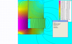
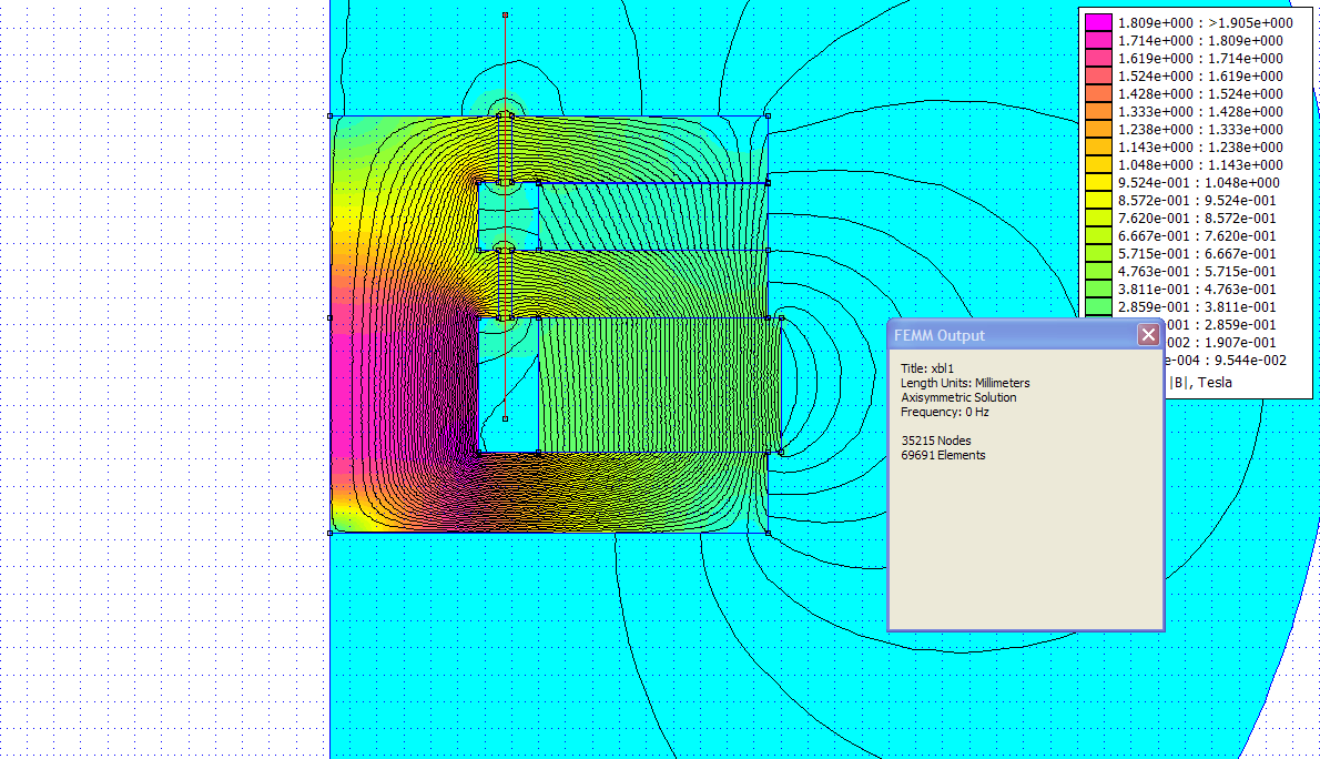
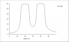
Next an XBL design:

not bad, better than overhung but not as good as underhung. however, it is possible that it generates more high order harmonics than UH/OH. this is why the THD is not representative. It reveals that something has a certain degree of harmonic distortion, but what harmonics? 2nd 3rd? Here high harmonics are generated (in theory) but (i'm skeptical) i would be curious in real-world examples.
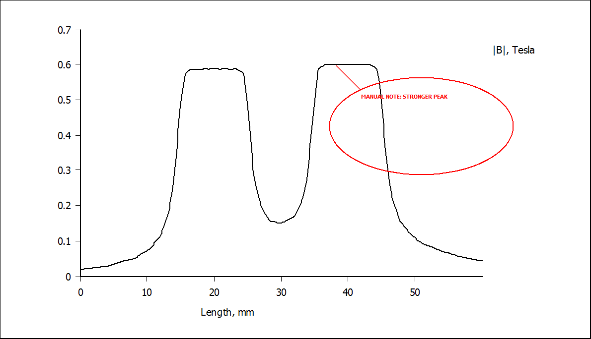
btw. i think the xbl is a clever one, but let's see what happens when the voice coil is 'mis-wound' :
see the peak in the BL curve?
it requires careful engineering. IMO top plates should not be made of laminations like this:
This might worsen the reluctance and more flux will flow on the low reluctance path.
The problematic part in a finished subwoofer that you won't be able to authentically measure BL distortion because of the suspension. It requires special machines. Therefore i'm trying to predict BL distortion as much as possible.
...
not bad, better than overhung but not as good as underhung. however, it is possible that it generates more high order harmonics than UH/OH. this is why the THD is not representative. It reveals that something has a certain degree of harmonic distortion, but what harmonics? 2nd 3rd? Here high harmonics are generated (in theory) but (i'm skeptical) i would be curious in real-world examples.
btw. i think the xbl is a clever one, but let's see what happens when the voice coil is 'mis-wound' :
see the peak in the BL curve?
it requires careful engineering. IMO top plates should not be made of laminations like this:
This might worsen the reluctance and more flux will flow on the low reluctance path.
The problematic part in a finished subwoofer that you won't be able to authentically measure BL distortion because of the suspension. It requires special machines. Therefore i'm trying to predict BL distortion as much as possible.
...
Attachments
-
 2_xbl_flux_bad.png12.5 KB · Views: 416
 -
 2_xbl_bad.png80.9 KB · Views: 526
 -
 2_xbl_blcurve_bad.png44.6 KB · Views: 421
 -
 2_xbl_blcurve3 14mm.png49.7 KB · Views: 416
 -
 2_xbl_blcurve2 10mm.png48.1 KB · Views: 433
 -
 2_xbl_blcurve.png45.5 KB · Views: 441
 -
 2_xbl_flux.png10.2 KB · Views: 425
 -
 2_xbl.png84 KB · Views: 420
OOps, gave you the wrong link. The distortion figures are in post #12 of this one:Nice drivers! with good sensitivity.
(It would be great if manufacturers could share the details of copper wires, diameter etc..)
Thanks for the info.
Never used tapped horns, have to do some research before i can comment on it. Pretty backwards mounting 🙂
What kind of software is that you used there? If there are distortion measurements for pure sine waves, they are so interesting 🙂
p.s. this is the first time I saw h0 as "EtaZero" in a datasheet
http://www.diyaudio.com/forums/subwoofers/185588-keystone-sub-using-18-15-12-inch-speakers.html
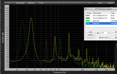
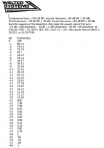
I used the Smaart program to look at the actual distortion speakers have when driven with a sine wave tone , an example showing 35 and 45 Hz at 77.5 volts(1500 watts in to a nominal 4 ohms) is posted below.
Using the distortion calculator harmonic distortion levels can be determined.
Slowly.
Attachments
Last edited:
Super info.
Both 2nd & 3rd harmonic @ -28dB and 4nd & 5th harmonics @ -40dB, 7th @ -51dB, close to inaudible above 400hz.
This is at xmax i suppose?
The tricky part is that you cannot tell the contribution from the suspension.
Does a Klippel reveals that?
Both 2nd & 3rd harmonic @ -28dB and 4nd & 5th harmonics @ -40dB, 7th @ -51dB, close to inaudible above 400hz.
This is at xmax i suppose?
The tricky part is that you cannot tell the contribution from the suspension.
Does a Klippel reveals that?
I really have no Klippel experience, just have heard others write about it, and how the B&C neo drivers have the best BL charts.Super info.
Both 2nd & 3rd harmonic @ -28dB and 4nd & 5th harmonics @ -40dB, 7th @ -51dB, close to inaudible above 400hz.
This is at xmax i suppose?
The tricky part is that you cannot tell the contribution from the suspension.
Does a Klippel reveals that?
They also use a very interesting coil winding topology, the details of which I have forgot.
I suspect B&C drivers are designed with simulations, then tested to see how they vary from the (proprietary) sim, after many tests the sim can be tweaked to closer match reality.
Fewer test iterations are probably required for each new model as the software is tweaked generation to generation.
The Keystone excursion maxima is right around 45 Hz, at 77.5 volts it would be around Xmax (Xvar), 30 mm peak to peak.
At 35 Hz, the excursion is probably only about 8mm peak to peak.
The suspension really puts the brakes on excursion above Xvar, the BC18SW115-4 would probably burn up before it hit Xlim.
Although I did not measure distortion, the driver sounded OK at 120 volts 60Hz, three times in a row (it was testing mistake), about 1 second per time.
Last edited:
Interesting, Weltersys,
i will read through the Keystone Sub thread you posted before.
Understand. sure they have their proprieraty stuff for sims.
Progressive spiders are extensively used in subs.
According to Klippel's paper
http://www.klippel.de/fileadmin/kli...Diagnosis_and_remedy_of_Nonlinearities_00.pdf ) and Hutt's patent
https://docs.google.com/viewer?a=v&...nxlcXVpdHlzbmRpbnZ8Z3g6N2FhNjY3NTNiY2Y5MDUyMw
a regressive spider is better in linearity.
At worst case the distortion of the suspension could be measured separately. A spider compliance measurement machine may be present at manufacturers. I'm wondering whether it is able to measure distortions too.
I may have an idea about better coil winding topology, i will come up with the details in a few posts.
--------------------------
Here is a split-coil model.
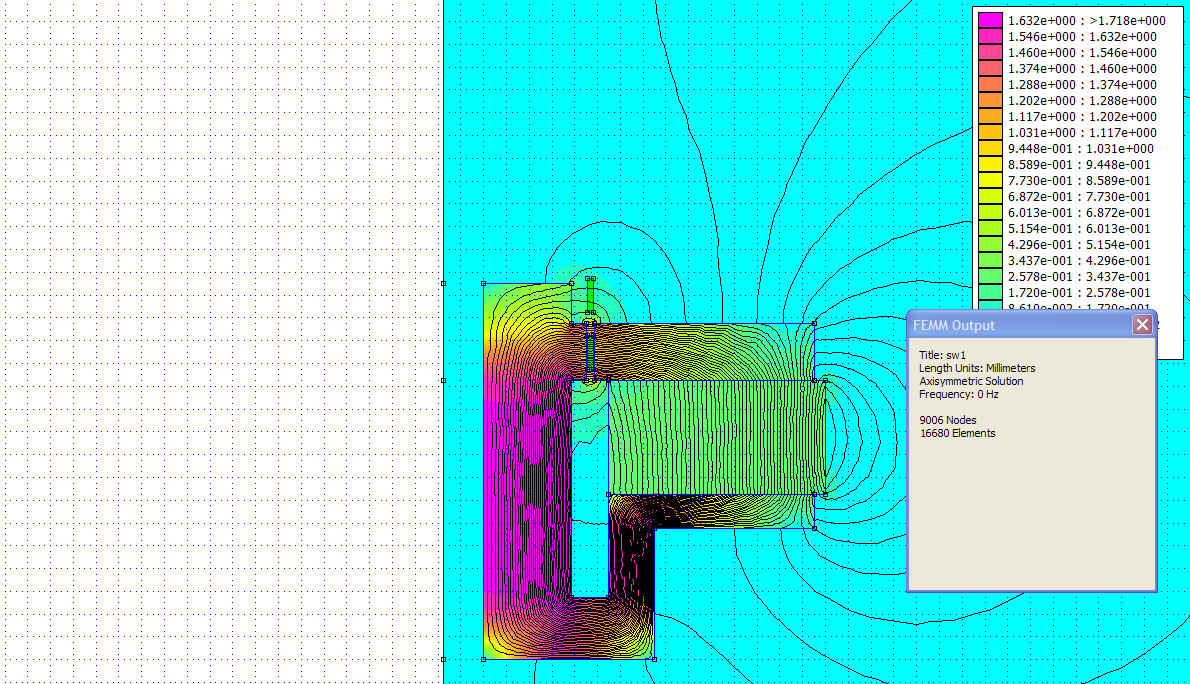
First I tried it on the existing flux curve of the optimized subwoofer and got worse results:
was sceptical and did the Bl curve evaluation in FEMM, the result were the same:
mm BL
5 5.54122
4 5.70404
3 6.03851
2 6.35937
1 6.46567
0 6.48344
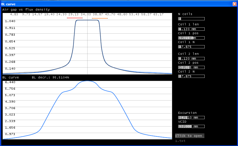
then I realized that a split-coil model is quite sensitive, it does matter were you put the coils and how:

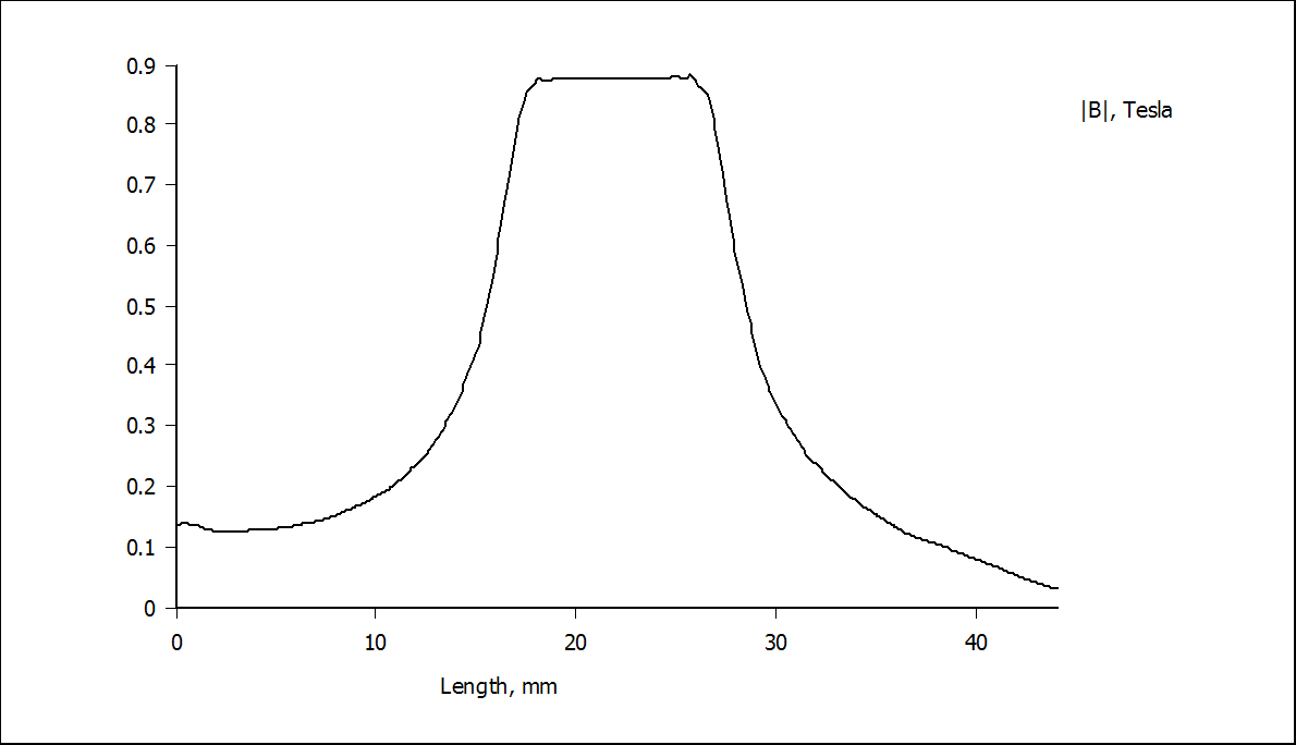
so, here is a newer FEMM model for split coils, and the flux curve, the result is generally good:
...
i will read through the Keystone Sub thread you posted before.
Understand. sure they have their proprieraty stuff for sims.
Progressive spiders are extensively used in subs.
According to Klippel's paper
http://www.klippel.de/fileadmin/kli...Diagnosis_and_remedy_of_Nonlinearities_00.pdf ) and Hutt's patent
https://docs.google.com/viewer?a=v&...nxlcXVpdHlzbmRpbnZ8Z3g6N2FhNjY3NTNiY2Y5MDUyMw
a regressive spider is better in linearity.
At worst case the distortion of the suspension could be measured separately. A spider compliance measurement machine may be present at manufacturers. I'm wondering whether it is able to measure distortions too.
I may have an idea about better coil winding topology, i will come up with the details in a few posts.
--------------------------
Here is a split-coil model.
First I tried it on the existing flux curve of the optimized subwoofer and got worse results:
was sceptical and did the Bl curve evaluation in FEMM, the result were the same:
mm BL
5 5.54122
4 5.70404
3 6.03851
2 6.35937
1 6.46567
0 6.48344
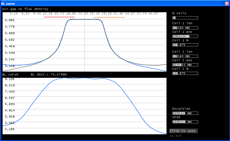
then I realized that a split-coil model is quite sensitive, it does matter were you put the coils and how:
so, here is a newer FEMM model for split coils, and the flux curve, the result is generally good:
...
Attachments


Good work with that keystone design Art,
Since i'm not exclusively interested in OBs, i may build the design one day
---------------------------------------
Next a JBL differential drive structure:
As expected, the even ordered harmonics are very low in level due to the symmetry,
Note that the flux curve is evaluated for 0A. If we set the current to 1A, we basically arrive to the same BL curve as would give by FEMM:


The BL curve is no longer symmetric as well as the flux curve.
(at post #1 i mentioned that the BL curve evaluated by FEMM is not symmetric, and also depends on the direction of the current. however, in real world we never use loudspeaker drivers with DC current, therefore - IMO - evaluating the BL curve without taking the DC currents into account is not problematic. i.e. we can evaluate the flux curves for 0A. so the application won't take the the coil's own field into account, this is why it's simplified)
Since i'm not exclusively interested in OBs, i may build the design one day
---------------------------------------
Next a JBL differential drive structure:
As expected, the even ordered harmonics are very low in level due to the symmetry,
Note that the flux curve is evaluated for 0A. If we set the current to 1A, we basically arrive to the same BL curve as would give by FEMM:
The BL curve is no longer symmetric as well as the flux curve.
(at post #1 i mentioned that the BL curve evaluated by FEMM is not symmetric, and also depends on the direction of the current. however, in real world we never use loudspeaker drivers with DC current, therefore - IMO - evaluating the BL curve without taking the DC currents into account is not problematic. i.e. we can evaluate the flux curves for 0A. so the application won't take the the coil's own field into account, this is why it's simplified)
Attachments
-
 3_jbl_blcurve3_1A.png42.8 KB · Views: 394
 -
 3_jbl_blcurve2_1A.png47.1 KB · Views: 402
 -
 3_jbl_blcurve3.png43.2 KB · Views: 400
 -
 3_jbl_blcurve2.png46.4 KB · Views: 391
 -
 3_jbl_blcurve.png48.4 KB · Views: 406
 -
 3_jbl_flux.png7.9 KB · Views: 381
 -
 3_jbl.png77.1 KB · Views: 441
 -
 3_jbl_flux_1A.png7.9 KB · Views: 371
Last edited:
- Status
- Not open for further replies.
- Home
- Loudspeakers
- Subwoofers
- BL distortion prediction / analysis in subs