Four years ago I uploaded a front end daughter card called "IPS6" for the M2x amplifier. IPS6 needed a matched pair of Nchannel JFETs (Fairchild J113s) whose Vgs values are identical when each one has a drain current of 3.00 milliamps. I know, I know: that's extremely specific. But that's what this daughter card happened to require.
The JFET matching fixture was revealed in M2x post #3377. Beware, it's not a printed circuit board; it requires a regulated DC power supply of 20.0 volts instead of a 9V battery; and you have to manually calibrate it (dial a 25 turn trimpot) to ensure exactly 3.00 milliamps is applied to the Device Under Test. But hey, at least it's one way to match JFETs. Feel free to change it however you wish, if what you want doesn't happen to be [ matched-Vgs when Ids=3.00mA ]. Be creative; innovate; explore the unknown; embrace the unorthodox.
The JFET matching fixture was revealed in M2x post #3377. Beware, it's not a printed circuit board; it requires a regulated DC power supply of 20.0 volts instead of a 9V battery; and you have to manually calibrate it (dial a 25 turn trimpot) to ensure exactly 3.00 milliamps is applied to the Device Under Test. But hey, at least it's one way to match JFETs. Feel free to change it however you wish, if what you want doesn't happen to be [ matched-Vgs when Ids=3.00mA ]. Be creative; innovate; explore the unknown; embrace the unorthodox.

It might be a good idea to rephrase the question-- to make it more general and more open ended (?) Perhaps something like
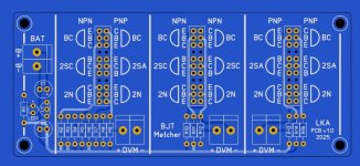
Does anyone see a way to make this BJT Simple Matcher PCB, match other types of semiconductor devices besides Bipolar Junction Transistors? Does anyone see a way to make this PCB match JFETs?
Hello,
Last night I took a look at the the PCB that you kindly gave us at Burning Amp last month. I also took a look at the circuit posted. The circuit shows the voltage delta being measured across a pair of current sensing resistors. Also noted the BJT base and emitter test pins are connected together.
From the data base, jFET Idss is measured with the gate and source connected together, same as the BJT b and e are connected on the SM test PCB. So there you go, to match jFET's place a reference jFET where the reference BJT would have been and a jFET to be tested in the matching location on the Simple Matcher.
A added note: You can also match a complimentary jFET (equal Idss at the test voltage) by plugging it into the other set of test pins.
Thanks DT
The test voltage can be adjusted by bypassing the regulator and using your test bench power supply.
Last edited:
Completely removing the voltage regulator IC represents legitimate out-of-the-box thinking, congratulations. When you eventually do use this PCB to match JFETs, please let us know here, and show the precision-of-matching results you were able to achieve.
I expect the first few JFETs to be tested may be damaged or destroyed, while you get accustomed to the requirement that an Nchannel JFET's gate needs to be connected to the more negative of drain & source, while a Pchannel JFET's gate should be tied to the more positive of drain & source. I can even imagine there's a 50-50 chance that you'll decide to perform NJFET matching by plugging the parts into the sockets labeled "PNP" on the BJT Simple Matcher -- which may be terribly confusing for the first hour or two. Ntype parts in Ptype sockets??? Let's hope that won't be necessary.
I expect the first few JFETs to be tested may be damaged or destroyed, while you get accustomed to the requirement that an Nchannel JFET's gate needs to be connected to the more negative of drain & source, while a Pchannel JFET's gate should be tied to the more positive of drain & source. I can even imagine there's a 50-50 chance that you'll decide to perform NJFET matching by plugging the parts into the sockets labeled "PNP" on the BJT Simple Matcher -- which may be terribly confusing for the first hour or two. Ntype parts in Ptype sockets??? Let's hope that won't be necessary.
Mark,
Thanks,
Okay I will report back after matching some JFET parts.
In terms of confusion and complexity, when I looked at your PCB circuit I said oh that is a Wheatstone bridge. I sketched it as a diamond in my lab book. I did not include all the labels; PNP, NPN or BJT. Then I said, N & P type jFET's have polarity. Then I sketched zoomed in details of the correct polarity of the N & P parts in the test sockets.
The confusing part for me is coming back a couple of months later and doing it again without my sketches.
Thanks DT
Just now I have edited post #1 of this thread. I added paragraph 6 called "AIR LOCK BOX" , and I apologize that it took me so long to remember this piece of the Q&A.
Where's my "That was easy" button at.....
Went together fast. Now I just need to wait for my 100qty BJT's to match.
As a way to pay forward @Mark Johnson 's generosity, I have 3 extra "completion kits" for folks who already have the PCB board + female headers handed out by Mark at BAF (or I suppose grabbed some from a board house). I will ship to you inside the continental US for free and you can pay forward to someone else down the road. @uptownsquash has one reserved if he'd like as I know he was at BAF for the talks. Do I have two more greedy boyz interested in the kit who already have the PCBs on hand?


[EDIT] Reserved:
@uptownsquash
@wg45
All of the giveaway BJT Simple Matcher parts kits have now been spoken for.
I have BJT Simple Matcher full kits (parts and pcb's) up in the swap meet for anyone interested.
I'll also be working on a 3D print design to use as an "Air Lock Box" for the BJT Simple Matcher. I will post print files once I've optimized the design with some iteration on prototypes.
Last edited:
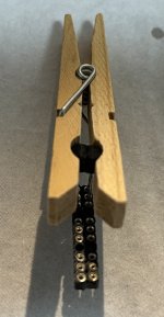
First time ever matching transistors. The BJT Simple Matcher works great. I'm using a little 4oz cup as an "Air current shield" currently. I plan to build a little 3D printed cap eventually. Since my work bench is right under an air vent the shield from air currents does help out with consistent measurements.
Lots of fun and lots of learning for a noob like me. I love it!
Thank you Mark!
Here's a little 3D printed "air current shield" design that fits nicely over the BJT Simple Matcher to help with consistent measurements on a drafty bench area.

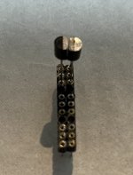
Here's what I had rigged up prior to making the 3D print design. It also worked fine, but not as clean.

Here's what I had rigged up prior to making the 3D print design. It also worked fine, but not as clean.
Last edited:
I'd be down for a couple. 🙂I can organize a GB down the road if there is interest!
jeff
Here's a shared cart anyone can use to order the BJT Simple Matcher Parts.
It does not include the 9V battery leads, which aren't on the BOM, but certainly come in handy. It also doesn't include any hex standoffs (kits at bezos bookstore) if you want to give it "feet".
https://www.mouser.com/ProjectManager/ProjectDetail.aspx?AccessID=3afe689cbe
It does not include the 9V battery leads, which aren't on the BOM, but certainly come in handy. It also doesn't include any hex standoffs (kits at bezos bookstore) if you want to give it "feet".
https://www.mouser.com/ProjectManager/ProjectDetail.aspx?AccessID=3afe689cbe
Last edited:
Hello,
Just for fun I purchased a little sit on the benchtop thermometer.
When I got up yesterday it was 63 Degrees on my benchtop. By the time the furnace was moved up from the over night setting and over the day we had warmed up the kitchen downstairs the little thermometer on the bench read just at 74 Degrees F. Now the furnace is set back to the over night set point of 63 Degrees F.
These little T-92 transistors are temperature sensitive little buggers. You know even with my expensive 6- 1/2 digit SMU's I do not expect to measure much better than a digit and a half accuracy. Just turning on the heat and going down the make scrambled eggs invalidates the measurements made before the coffee finished brewing.
Thanks DT
That's a very helpful observation DT.
Temperature is the key factor in making good matches from my limited experience. I can confirm as well that best matching is done all in one sitting so as to ensure temps are as stabilized as much as possible. Very sensitive little buggers indeed.
Best to match BJTs with consistent temps.
My home goes to 50°F on the thermostat when no one is home and when I get back from work at the end of the day, it takes a good 2 hours for my house to warm back up. I've observed that the bjt matching changes significantly if not done at the same temps. However, I have confirmed that making eggs does not invalidate measurements as long as the overall temp is relatively stable/similar. I made hard boiled eggs as reference. One can always recheck matches for a project to confirm if they still match well even if they are originally done at different times/days.
Last edited:
My version (only design, not finished product). I combined it with NPN-PNP matcher from Elvee. https://www.diyaudio.com/community/...tary-transistors-matcher.420932/#post-7865896
Attachments
I only bought the Aicevoos 98d so I could bring it to the Burning Amp Festival. I wanted to show people that it is easy to buy a 4.5 digit handheld meter with 0.1% basic accuracy, and which will display 0.01 millivolts, for a comfortably low price. I happened to stumble into a sale price of 20% off, completely by accident.
Do I use this meter very much? Not really. I've got a Keithley 193A 6.5 digit desktop multimeter when I need ultimate accuracy, and a Brymen 869s when I need handheld + accuracy. Also, like many hobbyists, I own several other no-name handheld DVMs from Amazon, for those rare occasions when I need to measure one current and three voltages simultaneously. I guess the Aicevoos will go on the top of that pile, the best of the second string meters.
Do I use this meter very much? Not really. I've got a Keithley 193A 6.5 digit desktop multimeter when I need ultimate accuracy, and a Brymen 869s when I need handheld + accuracy. Also, like many hobbyists, I own several other no-name handheld DVMs from Amazon, for those rare occasions when I need to measure one current and three voltages simultaneously. I guess the Aicevoos will go on the top of that pile, the best of the second string meters.
On amazon for $32, it is cheap. That Keithley is a beast! I have an old Fluke 8010a I inherited, not sure if it is true rms, and a 117 handheld. Also a Simpson 260, rarely used, but beautiful to look at!
Yes, temperature is a key factor when working with BJT's. Here is more :
https://www.diyaudio.com/community/...all-this-vbe-stuff-anyhow-part1-2-pdf.254781/
Sadly, I don't see Figure1 & figure2 in part one, both are wery important to understand all this Vbe stuff. Maybe somewhere is a copy with this figures?
For a native english speaker this should be more easy to understand than for me. Read it two or three times if necessary. For some members this is obviously too simple and there is not much about Hfe, only some words.
- Home
- Amplifiers
- Solid State
- BJT Simple Matcher -- test jig presented at 2024 Burning Amp Festival