I’m trying to work out the best way to supply heater voltage to eight JJ E88CC or EH 6922 via PCB. AC is right out. Regulation is unnecessary (and wasteful). There are totem poles in the circuit, and while I don’t necessarily have to elevate the heater supply, I hear it’s good practice with an eye towards cathode lifespan. Doing it bipolar seems to make more sense than stacking the heater voltage atop a reference voltage. Luckily, two diode drops and two Vbe drops get me from rectified potential back down to filament spec. My lack of a center tap does complicate things.

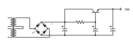
R and C values are generic for scale. That’s millifarads, not micro. I didn’t draw the RFI stuff and inrush current limiting on the primary, but it’ll be there.
Do I need loads from my new rails to the reference voltage? At the 7.5V mark, the 6.3V mark, or from the bases? Could I nix the center reference entirely after the rectifier and just cap across the rails? Any suggestions for the right NPN / PNP pair in through hole? Are there significant advantages in moving to a Sziklai approach in this capacitance multiplier application?

@rayma Thank you.
Can I parallel diodes in the bridge, or should I be looking at a ready-built bridge designed for industrial applications?
Amirite that series secondary would leave me with 3A available @ 12.6VAC, vs 6A @ 6.3VAC as drawn?
And re: that last sentence, are you inferring that I would reference to ground? I’m unclear. Or…maybe you’re just saying there would be less ripple and I could get away with a single bipolar RC stage…
Aaaaaand if I redraw this as a 12.6VAC situation (which gives me a CT, handy), would I double series the bridge diodes and use darlingtons on the new rails?
12.6 x 1.41 – (4 * 0.7) – (4 * 0.6) = 12.6 i think
12.6 x 1.41 – (4 * 0.7) – (4 * 0.6) = 12.6 i think
I would use a ready built bridge to make life easier. Something with a 25 or 30 amp rating is easy to get. You can’t parallel diodes unless they are a perfect match and even then one will hog the power and blow! You’re wasting a lot of power as heat using those resistors too. You might just want to get a DC to DC converter off the net and feed it unregulated DC and dial in your 6.3 volts out. They are relatively low noise and can handle plenty of amps output.
I'd use one of those 30A quad bridges that mount to the chassis for a heat sink.
https://www.digikey.com/en/products/detail/solid-state-inc/MB3505/14547781
The transistor will also need a heat sink.
Since the circuit is floating, you can reference the output to any node you want.
One circuit with 12V output, like this:
https://www.digikey.com/en/products/detail/solid-state-inc/MB3505/14547781
The transistor will also need a heat sink.
Since the circuit is floating, you can reference the output to any node you want.
One circuit with 12V output, like this:
Attachments
Whoa, I always assumed that that would cause current draw on the Vref. No? Also, no connection to the CT?Since the circuit is floating, you can reference the output to any node you want.
One circuit with 12V output, like this:
Is uneven heater wear a concern with single supply DC, or just handwringing from some post somewhere?
My concern would be that there's too little Vce for the BJTs to work with (almost equal to Vbe which is only 0.6V). Unlike a capacitor, a transistor can only pull down the peaks but not fill the valleys. If you take the ripple into account, like the valleys of the ripple could dip to as low as 7 volts under large currents, that makes the regulation really awful.
I would use a Schottky bridge rectifier and then add one or two diode drops before the 1mF capacitors. This gives the BJT more headroom to regulate.
I would use a Schottky bridge rectifier and then add one or two diode drops before the 1mF capacitors. This gives the BJT more headroom to regulate.
Whoa, I always assumed that that would cause current draw on the Vref. No? Also, no connection to the CT?
No connection to the center tap, this is for 12V, not 6V.
For current to flow, you need two connections, not just one. The filament circuit is floating.
So one of the 12V output nodes can be connected anywhere without problems,
within the tubes voltage limit of Vgk.
I don't know if full wave bridge instead of CT would give you more voltage. Your trading transformer efficiency against diode drop.
No connection to the center tap, this is for 12V, not 6V.
Ah, I see I was being confusing. I was referring to the way we elevate AC heaters in the simplest sense, by feeding the Vref into the CT of a 6.3V or 12.6V winding. Do I understand correctly (now) that if I’m rectifying to DC, that the CT of the winding is universally ignored, and the Vref is only attached to the negative output of the rectifier (if single supply) or only attached to the center of the capacitors (if bipolar)? I’ve been assuming that I have to treat Vref the same as chassis in a bipolar scenario, attaching both to the center of the capacitors and to a CT (or via a resistive split to both ends of the winding if no CT available).
Last edited:
What sort of current are you pulling here? Is your heatsink the chassis? What’s the ripple like under your full load?
Ah, I see I was being confusing. I was referring to the way we elevate AC heaters in the simplest sense, by feeding the Vref into the CT of a 6.3V or 12.6V winding. Do I understand correctly (now) that if I’m rectifying to DC, that the CT of the winding is universally ignored, and the Vref is only attached to the negative output of the rectifier (if single supply) or only attached to the center of the capacitors (if bipolar)?
Ignore the CT.
The Vref goes to the OUTPUT node of the filament supply (either one).
Took me a minute to follow this but I’m picking up what you’re putting down. I might have to look at ripple IRL with increasing bulk cap value, since even with the headroom saved moving to a schottky bridge, I’d still be working on the margins. Why do you suggest a diode drop over an attenuator made from the series R and an R from base to Vref?My concern would be that there's too little Vce for the BJTs to work with (almost equal to Vbe which is only 0.6V). Unlike a capacitor, a transistor can only pull down the peaks but not fill the valleys. If you take the ripple into account, like the valleys of the ripple could dip to as low as 7 volts under large currents, that makes the regulation really awful.
I would use a Schottky bridge rectifier and then add one or two diode drops before the 1mF capacitors. This gives the BJT more headroom to regulate.
Well, it's because a diode can provide adequate reference voltage to the BJTs. I didn't notice that it was supplying as high as 3A so my previous thoughts might not be correct, but let me analyze it more carefully anyways. In your original circuit (excuse me for referring the center point as "ground" for simplicity):

If the load requires 3A and Q1 is capable of hFE=1000 (which is already VERY optimistic), the current through the base will roughly be 3mA, which is 0.9V drop from point A to B. Adding the Vbe=0.6, the voltage between point A and C will be at least 1.5V. If you need 3.15V (half of the required 6.3V) at point C, the valleys of the rippled DC input at point A has to be 1.5+3.15=4.55V and a total rail-to-rail voltage after the rectifier bridge of 4.55x2=8.9V. The reality will only be worse, because
(1) There's no such BJT with a hFE=1000 at Ie=3A. Commonly used devices are around 100, which means the voltage drop across R1 to R3 will be 9V (What? That's rather impractical to get 6.3V out of a more-than-20V power supply!). Either use a Darlington or MOSFET, and rely on a zener or resistor to ground from point B for reliable DC path rather than the load-dependent Ib or gate leakage.
(2) Even if there is one, the higher the hFE the lower the Vce will be. Under the previous conditions, the Vce=1.5V is still not enough for the transistor to work with the greatest linearty. Hope for at least 2~3V with normal devices.
A single transistor doesn't have enough current gain to work under such a setup without any serious voltage drop, but a serious voitage drop means much higher supply voltage. If at any time the voltage across C1 sags below Q1 could handle (and Q1 saturates), there will be sharp harmonics of valleys appearing in the DC output, and would be even more problematic than AC heater supply.
- Home
- Amplifiers
- Tubes / Valves
- Bipolar Cap Mult DC Heaters