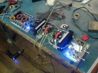
my biggest T-amp. 🙂
I designed it to do 600W per channel into 2 ohms based on 41Hz's amp8.
note: first time to attach pics so hopefully it would come out.....
(edit: it did come out....good! 🙂 )
the case is estimated to be about 7" wide, 29" long and slightly taller than 2".
this will be a big car amp.
I designed it to do 600W per channel into 2 ohms based on 41Hz's amp8.
note: first time to attach pics so hopefully it would come out.....
(edit: it did come out....good! 🙂 )
the case is estimated to be about 7" wide, 29" long and slightly taller than 2".
this will be a big car amp.
Attachments
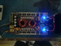
control PCB which has the aux SMPS for +/-15V for the op amps, 5V for the logic control (delayed signal for mute) and the amp8 chipset. also has preamp for added gain for weak sources and bass boost. 🙂 also has a temp control for the fans soon to be added in the final case.
(red cap used for covering LED......too much glare. 🙂 )
(red cap used for covering LED......too much glare. 🙂 )
Attachments
Nice job! Looks like a beast. Did you make the SMPS and control PCB? What speakers do you plan on driving?
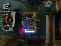
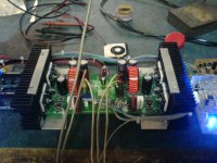
yep. the SMPS PCB has a small daughterboard that holds the PWM oscillator and driver (same with the aux supply) so the main PCB holds all high current stuff. the main PCB was drawn by hand.
main SMPS high current terminal blocks were hand made using hand tools. 🙂 I can't find anything that could handle the current over here.
the control board was made using EAGLE and photoetching.
so far, I have tested it on full range and it sounds good. but it will be driving two Kicker comp VR subs in parallel 4 ohms bridged.
the same circuit that I posted in my website (www.djquan.angelcities.com/smps.html) but with different mosfet drivers. the one I used in that SMPS used totem pole drivers.

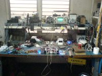
yeah, I just noticed that it got into the pic when I posted it already. 😛 I think I have to change it someday. it blinds me when I'm drilling something.
it WAS battery powered. the 6V battery failed so I rewound the motor to run on 12V and added wires and clamps to a SMPS or car battery. it's a good thing to not need to drag long extension cords in the garage.
it WAS battery powered. the 6V battery failed so I rewound the motor to run on 12V and added wires and clamps to a SMPS or car battery. it's a good thing to not need to drag long extension cords in the garage.
BTW guys, I'm having a bit of a issue on the output and it worries me a bit.......
the output signal contains a constant sine wave of about 5V peak at 625kHz (the idle freq) it is a bit high for my liking and I'm wondering if it would cause havoc of my car's engine computer or other stuff.
the output inductor measures about 10uH and the 5W zobel resistor along with the main inductors get a bit warm to the touch but not hot. you can just feel it get a bit warm.
also, I'm not sure if it is normal with high power T amps since my amp2 also has the same problem but one channel has 3V peak and another at 4V peak. I originally thought it was due to the inductors wound with some turns overlapping so I rewound it (now with litz wire) and it still had the same problem.
it doesn't seem to affect the sound quality though.
when this amp is done, this will power my current subs and the amp2 will be moved to the front separates and my P3A amp to the rears. this concerns me since the speaker wires run along the door sills along with the stock wiring. wondering if the high freq sine waves will be coupled and interfere with the car's electrical stuff.
Try increasing the value of the filter inductors. What value caps are you using in the output filter and what load impedance will the amp be driving?
I can't recall but they are the stock values provided and I think are 0.1uF and 22ohms + 0.22uF for the zobel circuit.
I hope it's not a 0.1uF cap. It should be more like 0.47uF.
You can try to get some toroid cores with a higher permeability so you can get higher inductance without overlapping the windings.
22 ohms for a zobel/snubber is fairly high, but if it's rated at 5W and it's only getting warm then there's nothing to worry about.
You can try to get some toroid cores with a higher permeability so you can get higher inductance without overlapping the windings.
22 ohms for a zobel/snubber is fairly high, but if it's rated at 5W and it's only getting warm then there's nothing to worry about.
BWRX said:I hope it's not a 0.1uF cap. It should be more like 0.47uF.
You can try to get some toroid cores with a higher permeability so you can get higher inductance without overlapping the windings.
well, I do remember that it is 0.1uF in parallel with the load. I could try placing another cap in parallel right on the speaker terminals?
the main problem here is that toroids (of any type) is hard to come by here let alone specialized types so I would like to use the stock cores as much as possible.
That 0.1uF isn't the capacitor I was talking about. The caps I'm talking about are the C in the LC filter. They're connected between the output inductor and ground and should have a value around 0.47uF. I don't know what type Jan supplied with those kits.
Technically, the 0.1uF in parallel with the load is part of the output filter though.
Technically, the 0.1uF in parallel with the load is part of the output filter though.
that I what I was talking about. 🙂 they are mounted on the PCB. they are film types at 100V.
maybe another cap across the speaker terminals (0.47uF) would help? I could try that this weekend. or should it be that the 0.47uF cap be mounted right on the PCB?
maybe another cap across the speaker terminals (0.47uF) would help? I could try that this weekend. or should it be that the 0.47uF cap be mounted right on the PCB?
- Home
- Amplifiers
- Class D
- Big-t