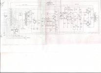
I just got this amp from a Thomas organ and while checking voltages I found that I have no voltage on the bias line. The schematic shows I should have -15v but my meter reads 0. I have only turned it on for a short time but it did seem to work ok while it was on. I did have the 25vac but I get +35vdc on the + side of C702 but 0 on the other end when it should be -15. What would cause this?
Attachments
Where are you taking your measurements with reference to? Where is the black (neg) probe sitting when you are taking your DC measurements?
Also, did you check all the transformer coils for the proper voltages?
Let us know and we can go from there.
Also, did you check all the transformer coils for the proper voltages?
Let us know and we can go from there.
Voltages are pretty much normally except that I don't have any negative voltage in the bias circuit. Its reads 0v from ground to any point from the grid resistors to R702. Schematic shows I should have -15v there.
Where does pin 1 and 2 go? (this might be important to why we are not seeing -15V)
It appears they are to bypass that 1M resistor or have some input into that line you are trying to measure.
Also do you get the correct labeled voltages around V7028?
It appears they are to bypass that 1M resistor or have some input into that line you are trying to measure.
Also do you get the correct labeled voltages around V7028?
I don't have the organ so I don't know where pins 1 and 2 went. I assume it went to some sort of tremolo control. After reading voltage again I am about 100v short on the B+ rail and I have 18v not 30v at pin 8 of V702B and still 0v on the bias rail.
That bias supply is unconventional (polite way of calling it weird).
They are trying to make 1 circuit do 2 jobs ... in a way that having trouble on one causes *big* problems in the other..
Bad engineering.
Main question is: will you use this in the original organ, as intended ?
In that case, connect the missing part and everything should go back to normal.
Yet, as I said, having a design that when you disconnect the preamp it kills the power tubes isn't my idea of reliability.
The 25+25VAC winding + diodes SD701 make a DC supply with unloaded voltage of 35V DC.
It's a *floating* voltage, not directly referenced to ground.
Now, if you ground it through R701 and connect the other end to some "mystery" point which sits at +15V , which "eats" 107mA, and voltage drops to 30V DC, then one end of C702 will also sit at +15V and necessarily the lower end will be at -15V.
A very "iffy" design, depending on a delicate balancing act to work at all.
Personally I would disconnect C107 "+" end from connector S701 pin 2, would ground it through another 140 ohm 5W resistor, so as to have a balanced and symmetrical load (basically I'm replacing the mystery elements at the other end of the connector) , now I will have the proper -15V bias and call it a day.
Good luck and post results.
I have never even seen the organ it came from and cant find any useful info it so the mystery parts remain a mystery. I had planned on using it as a guitar amp and usually would just gut the thing but I am curious to see how it sounds with the original tremolo and 6GK6 tubes. When I read voltages with tubes I get about 265 B+, with only the recto I am getting 420v B+, is that normal? It seems like quite a big difference. I don't see a C107, do you mean C702?
Last edited:
I installed the 140R and all voltages are right on. Now how can I can the tremolo to work again? Something was connected at S701 pin 1 and 4 but I don't know what. I also am not able to get a voltage reading at pin 8 of V702B, the schematic shows 30v there.
The trem doesn't work? get the oscillator running, it appears to be free-running. Zero volts on pin 8 or the tube? OK what is on pin 6. Says 300v, but if it is really high, then the tube is not conducting. Are both sides of that tube heaters running? it is a simple circuit, you opught to be able to solve that part. Then we need to get the interface running. I SUSPECT that the lines going off the page merely short across R711. That then allows the oscillator signal to couple to your bias feed via C703.
That bias supply is unconventional (polite way of calling it weird).
They are trying to make 1 circuit do 2 jobs ... in a way that having trouble on one causes *big* problems in the other..
Bad engineering.
I would completely agree - but the OP's problem is that the amp can't be used 'stand alone' as the bias voltage is dependent on whatever is connected to pin 2, and how much current it takes.
Easiest option would be to redesign the bias circuit sensibly, adding a small mains transformer, rectifier etc. and a preset to adjust the bias.
I have about 310 on pin 6 and I do have the 30v, it was just hard to get a reading for some reason. I can hear the tremolo thumping very lightly in the background but not in the signal, not noticeably anyway. I have shorted the 2 lines to bypass R711 and the thump is slightly more noticeable but just barely.
No, your unbiased tubes are passing excessive current and pulling +B down , but now you solved that.When I read voltages with tubes I get about 265 B+, with only the recto I am getting 420v B+, is that normal? It seems like quite a big difference.
Yes, sorry, I mistyped.I don't see a C107, do you mean C702?
Cool 🙂installed the 140R and all voltages are right on.
As of the tremolo, I think Enzo is spot on.
Being an organ, probably most of the circuit lives in a chassis in the bottom of the unit, but wires run to some control panel by the keyboard.
That's the part we're missing.
Don't you have the rest of the schematic?
Agree, and my first reaction was to redesign a conventional bias source, using that 25+25VAC winding already present.but the OP's problem is that the amp can't be used 'stand alone' as the bias voltage is dependent on whatever is connected to pin 2, and how much current it takes.
Easiest option would be to redesign the bias circuit sensibly, adding a small mains transformer, rectifier etc. and a preset to adjust the bias.
But then I got intrigued by the low value high dissipation R701 , which probably *is* needed for some other purpose (tremolo or feedback related?) so I preferred to "play along", simply connecting to that supply what it expected to see; another 140r 5W to ground.
It worked while keeping everything else stock.
It *is* a weird circuit after all 😉
No I do not have the rest of the schematic. I suspect the wires ran to a switch or a pot, but I have yet to even find a picture the organ where the controls are visible. Its does seem that the tremolo is working, I can hear it in the background but it is very faint. These old organs usually had a very intense tremolo effect.Could it just be a bad cap?
I managed to ahold of a more complete schematic and I can see the 2 mystery wires from pins 1 and 4 go to a vibrato on/off switch and a full vibrato switch. The lead from pin 1 also runs to a transistor vibrato unit in the tone generator, so I give up on the original circuit. What is a good tremolo circuit I can use with only 1/2 of a 12A_7?
- Status
- Not open for further replies.
- Home
- Live Sound
- Instruments and Amps
- Bias voltage problem