I would like to create a new bias tool and would like some feedback or suggestions for specifications. Initially I thought a maximum B+ of 900V and a maximum current of 500mA. The bias tool would measure the actual plate voltage, plate current and cathode current.
This is what I’m using now to bias my KT150 tubes:
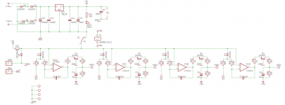
Bias automaat - Pagina 39 - forum.zelfbouwaudio.nl
Unfortunately it’s in Dutch, but you can find the diagram and ZIP-files there too.
It works great. I added a 60 seconds timer for allowing a positive voltage to the voltage reference diode. This will protect the tubes during the heating phase. The autobias board would try to force a higher current through not properly heated tubes, with possible damage.
Regards, Gerrit
Attachments
Additional information:
From each cathode to ground you need a resister (1 Watt) that determines the quiescent current.
Measure the voltage across the reference diode D5. For example a 1N4448 may give a voltage of 610 mV. The cathode current and resistor value are determined by the formula:
Reference Voltage / Cathode Resistor = Quiescent Current, for example 0.61 V / 6.1 Ohm = 100 mA (per tube)
I have PCB’s in order for this. The cathode resistors are not placed on this PCB but directly from cathode to ground.
Regards, Gerrit
What does B+ matter to this beast? B+ is what ever the amp supplies, yes? It could be that I miss something...
Also, amps that have a power tube idling at more than 200 mA are few. You'll get better resolution if your measurement window is smaller.
cheers,
Douglas
Also, amps that have a power tube idling at more than 200 mA are few. You'll get better resolution if your measurement window is smaller.
cheers,
Douglas
I guess too that cathode current measuring is most important. There is allways a relation between B+ and actual current, but you regulate using G1, not plate voltage.
Regards, Gerrit
Regards, Gerrit
My thoughts are to measure the plate voltage, plate current and cathode current. This way I can determine the output power of the tube as well as the bias current. This would be an octal socket adapter that would be placed between the amp chassis and the output tube(s). Bluetooth would send the data over to an Android app that would display the data. I know there are several of these types of devices out there but none use BLE and an Android app. Does this sound like a useful piece of test gear for biasing amplifiers?
I would like to create a new bias tool and would like some feedback or suggestions for specifications.
Before you get to voltages and currents, what exactly is the purpose of this tool and how would it accomplish that? Describe the desired functionality.
Starting a discussion with a poorly defined topic risks getting into the "garbage in, garbage out" category.
I thought my initial thread topic did this . . . the bias tool is used to set or adjust the bias of the output tubes in a guitar amplifier. Most tools like this simply measure the cathode current and offset the grid current to determine the plate current. They are typically connected to a meter with a cable.
The tool I am proposing will measure the actual plate current on the high side as well as the cathode/grid current. I would then subtract the plate current from the cathode/grid current and use the plate voltage to calculate the real bias level and output power. The data would be sent to an Android app using Bluetooth to display the readings.
These would be octal socket/plug type devices that would fit between the tube and socket on the amplifier chassis. The Android app would allow you to use one, two or four of these depending upon the amplifier requirement.
Sound interesting?
Measuring the matching or un-matching of the currents is not as easy as you might think.
For a push pull output transformer . . .
'Matching' for a Hi Fi Stereo (or for a Guitar 'mis-matching') all the Push and all the Pull currents is important.
For Pentode mode or Beam Power mode, Only the plate currents matter.
For Ultra Linear Pentode mode, or Ultra Linear Beam Power mode, Both the plate currents, And the screen currents matter, but not at the same percentage.
So if the percentage of plate and screen current of one tube is different than the plate and screen current percentage of the other tube is, You have to compensate for the Amp x Turns of each plate, and Amp x Turns of each screen current. (turns of plate is different than turns of UL tap).
And for this, you must know the percentage (%) of the UL taps.
This can be really complex (no not 'Operator J', just lots of measurements & multiplication of each one).
For Triode wired Pentodes, and Triode wired Beam Power, the cathode currents matter, since the plate + screen current = cathode current.
Since this was initially for a Guitar amplifier (See the admission of that in Post # 6), but it is on the Tubes / Valves threads, and not on the Instruments & Amps threads, I think I am allowed to give an answer for both . . .
For a Hi Fi Stereo amp, match all the amp x turns of both sides of all the primary windings . . . (Pentode/Beam Power; UL; or Triode wired).
For a Guitar amp, stop worrying about current matching, the guitar will probably sound better if the currents are unmatched.
Guitar Amp manufacturers could do us all a favor, put a 10 Ohm resistor in each cathode circuit to ground, and put in test points (one for each cathode, and one for ground), and give away a free $15 Analog Volt Ohmmeter. You could measure and see if you have a really bad performing tube (or you could just listen). But the manufacturers are either too cheap, or too brain dead, or both, to think of that.
Personally, if I were a performer, I would purchase the guitar amp that was easiest to test and repair (during my highly paid concert).
"Think out of the Box"
Just my opinions.
Can we set a record, and close the thread with only 10 postings?
My experience says no, but I am not a betting man.
Last edited:
These would be octal socket/plug type devices that would fit between the tube and socket on the amplifier chassis. The Android app would allow you to use one, two or four of these depending upon the amplifier requirement.
Sound interesting?
Not really. Before I did that I'd just get 3 free meters from HF and hot glue or velcro them to a small board and run the leads to your socket adapter. Set each meter to the E,I,R you want.
Last edited:
The tool I am proposing will measure the actual plate current on the high side as well as the cathode/grid current.
What grid current? Even if you have an AB2 amp, I sincerely hope you don't have any grid current at quiescent.
I would then subtract the plate current from the cathode/grid current...
Again with that "cathode/grid current". What does that mean? Cathode current is never the same as grid current. And you better never have grid current when you set bias. And if you subtract plate current from cathode current you get screen current. What are you going to do with screen current? And why subtract when you can just measure screen current?
...and use the plate voltage to calculate the real bias level and output power. The data would be sent to an Android app using Bluetooth to display the readings.
What is "real bias level"? As opposed to what? False bias level? And why do you need to calculate it when you can measure it?
What output power? Bias adjustment is made at idle. Output power at idle is zero.
These would be octal socket/plug type devices that would fit between the tube and socket on the amplifier chassis. The Android app would allow you to use one, two or four of these depending upon the amplifier requirement.
Those octal devices are sold on eBay. They only measure current because typically there is no need to measure anything else. But you can make or modify them to measure other things. As 20to20 said, a few cheap HF multimeters would do it.
If you want to make a complex tool as an exercise, that's great. Let's see it.
- Home
- Amplifiers
- Tubes / Valves
- Bias Tool