Hi Guys,
I had built the original AEM6000 (David Tilbrook) amp modules, power supplies, status monitors and surge current limiter many years ago.
I have now decided to finish this project by testing the amp modules before I install everything in its case.
On one amp module everything is good, bias current adjustment as per instructions is 2.6v across the 10ohm 5w series resistors.
However the other module can only be adjusted to 2.3v... I have changed the original 200ohm Phier trim pot with the same brand and spec - still only getting the 2.3v.
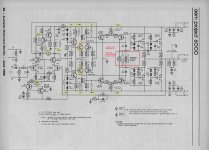
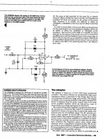
I have attached the circuit diagram with my measurements in green and maybe someone can give me some advice on what is going on.
Please note my wall voltage is around 248v AC.
Any help would be appreciated.
Peter
I had built the original AEM6000 (David Tilbrook) amp modules, power supplies, status monitors and surge current limiter many years ago.
I have now decided to finish this project by testing the amp modules before I install everything in its case.
On one amp module everything is good, bias current adjustment as per instructions is 2.6v across the 10ohm 5w series resistors.
However the other module can only be adjusted to 2.3v... I have changed the original 200ohm Phier trim pot with the same brand and spec - still only getting the 2.3v.
I have attached the circuit diagram with my measurements in green and maybe someone can give me some advice on what is going on.
Please note my wall voltage is around 248v AC.
Any help would be appreciated.
Peter
Attachments
Hook up the amplifier, no speakers, ground the input.
What voltages do you have across R41 and R43?
(They should be 2 or 3 millivolts.)
Also watch the temperature of your output transistors ... with no signal, room temperature is the rule.
The goal is to set the amp up with as little current in the output stage as possible, in keeping with minimal distortion. Too much current and things will get hot... really hot, really fast. Not enough current and you will get a crossover notch distortion which will be audible at very low volumes.
Hi Douglas,
No speakers connected, Input grounded.
Across R41 = 19.7mv R43 = 20.8mv (Output transistors get warm after 10mins)
Good module - R41 = 27.2mv R43 22.1mv (Output transistors get warm after 10mins)
HD - Both amp modules are using identical components.. If R35 = 100R and I need to change to 120R to be able to adjust the correct Bias current - Does that mean their is something else that is a problem in the circuit?
Thank you.
Peter.
It is the inevitable tolerance of the mosfets. They have very different threshold voltages, particularly if they are from different batches.
It is not a problem. The two output stages would have different trimmer values in operation anyway.
HD
It is not a problem. The two output stages would have different trimmer values in operation anyway.
HD
Mine is consistently above 245, it's only a few percent high.my wall voltage is around 248v AC.
Thank you all.
HD - I will go to Jaycar tommorow and pick a 120R resistor.
I really appreciate everyone's input.
Peter.
HD - I will go to Jaycar tommorow and pick a 120R resistor.
I really appreciate everyone's input.
Peter.
I don't think the mains voltage will have any significant effect on settings. There will always be small fluctuations, spikes, sags and surges in the line voltage and these are mirrored in both DC rails by the rectifier which should nevertheless maintain a steady average +/- balance of the power rails with respect to ground. That's what matters.
I think the OP included the figure for completeness and it shows attention to detail, not a bad thing for building a beast like this one
I think the OP included the figure for completeness and it shows attention to detail, not a bad thing for building a beast like this one
Increase R35 from 100R to 120R, then switch on and set the trimmer.
Problem solved.
HD
Thats what I did to mine.
Same issue. one channel was fine, other was a touch low.
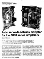
If you have issues with the DC offset David released a DC Servo board a little later.
With this I got mine to about 1mv dc.
Also made it so much easier to set the dc offset.
UserAbuser - I vaguely remember this board. Would you happen to a copy of the AEM magazine which had the DC servo board.
Peter.
Peter.
Hi Douglas,
No speakers connected, Input grounded.
Across R41 = 19.7mv R43 = 20.8mv (Output transistors get warm after 10mins)
Good module - R41 = 27.2mv R43 22.1mv (Output transistors get warm after 10mins)
HD - Both amp modules are using identical components.. If R35 = 100R and I need to change to 120R to be able to adjust the correct Bias current - Does that mean their is something else that is a problem in the circuit?
One of the reasons the voltage might not go up at that adjustment point is that the drivers it's feeding are saturated. While the idle current (approx 100ma) seems a bit high, I don't think it's a problem.
Guys,
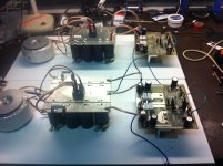
The 120R resistor works a treat. I have now set up the bias current to 2.6v as specified for both modules and have set the dc offset to around 8.6mv for both.
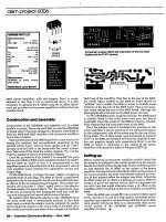
Attached is a photo of my temporary test bench setup of the AEM6000 amp modules and power supplies. Now I can go ahead and start installing everything in its case.
Thank you all.
Peter.
The 120R resistor works a treat. I have now set up the bias current to 2.6v as specified for both modules and have set the dc offset to around 8.6mv for both.
Attached is a photo of my temporary test bench setup of the AEM6000 amp modules and power supplies. Now I can go ahead and start installing everything in its case.
Thank you all.
Peter.
Attachments
Fantastic!!
A happy ending.......
Astro, I was around when David Tillbook penned his amplifiers in the ETI magazine. I built the ETI5000, but it was not a good amp and sounded harsh and gritty. Some years later I heard the ETI6000 and it was far, far better, in fact one of the best PP AB amps in the market at that time and better than most of the commercial domestic amps. It was used in a few proaudio situations too because of its good sound quality and relative low cost. But it was not particularly efficient and the second diff stage ran very hot. I know how he did it, now that I know about amps in detail, he used huge loop gain. That is another way of saying that he used a lot of global feedback - and what was amazing was the stability, no mean achievement. You may realise he was a Professor of Maths at Uni of Sydney, and the amp was a testimony of his mastery of control theory.
A very good amp...... keep it for decades, it's worth it........
Hugh Dean
Last edited:
Thanks Hugh.
I am happy that its all working now. I actually started building this amp back in 1986 and tried to use the best components available. Beyshlag resisters, polyproplene and mica film caps and recently added the nichicon Muse electrolytics. The four 0.22ohm 5w 5% resistors on the amp modules are non-inductive - Not sure if they will actually make any difference or not.
Sometimes life gets in the way and we go in other directions. I now have some free time and determine to complete this amp.
Thank you for all your advise.
Peter.
AEM 6006 DC Servo Feedback.
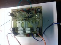
This board goes across near the middle of the board effectively blocking access to the central trimpot.
You will need to think about this for access for later adjustments.
I mounted the board at an angle, and also cut a notch into the edge of it to try and make it easier to get at the trimpot.
This board goes across near the middle of the board effectively blocking access to the central trimpot.
You will need to think about this for access for later adjustments.
I mounted the board at an angle, and also cut a notch into the edge of it to try and make it easier to get at the trimpot.
Attachments
Last edited:
UserAbuser - Thank you so much for supplying the article for the dc servo board.
I will call on my old pcb skills to make a couple of these boards.
Much appreciated.
Peter.
I will call on my old pcb skills to make a couple of these boards.
Much appreciated.
Peter.
Do you happen to have the original PCB layout in digital format (sprinlayout?)Guys,
The 120R resistor works a treat. I have now set up the bias current to 2.6v as specified for both modules and have set the dc offset to around 8.6mv for both.
Attached is a photo of my temporary test bench setup of the AEM6000 amp modules and power supplies. Now I can go ahead and start installing everything in its case.
Thank you all.
Peter.
- Home
- Amplifiers
- Solid State
- Bias adjustment problem on original AEM6000 amp