What I was trying to get across to the op was the basics in a simple to understand form.
Yes, i understand.
Multi choice 😀
You could argue both are correct or equally neither are correct. Not enough parameters are given to say either statement is true or false.
Being really - this is a well-known "last chance question" at exams in out semiconductor-physics or electrotechnic universities.
Just a question to start a talk, a way for teacher to check if one just learned or really have undestanded.
Base current in BJT is a recombination of minor carriers while emitter current mainly dependant of BE-voltage. But you're clever enough, both effects are tightly tied together, so common understanding dictates current controlled mode of BJT.
In this case FETs becomes current controlled too, because GS and GD capacitances demands a current to recharge and operate.
It's a lot easier to understand BJTs as voltage controlled devices...
Example: why does it take so long to turn off when you set base current to zero? Because Vbe controls the output current, so to turn it off Vbe has to go down, so charge has to be removed from it, so either suck the charge out with negative base current or wait for charge to fall through the emitter... Also transition frequency, etc.
Example: why does it take so long to turn off when you set base current to zero? Because Vbe controls the output current, so to turn it off Vbe has to go down, so charge has to be removed from it, so either suck the charge out with negative base current or wait for charge to fall through the emitter... Also transition frequency, etc.
Vertical mosfet (for switching) can have very low distortion. It depend on implementation.
http://cordellaudio.com/papers/MOSFET_Power_Amp.pdf
Fig. 15b (fundamental notched out) on page 13 of the mentioned PDF file shows an extrem low value of THD+N - unfortunately I note saw tooth character for the residual diatortion. Maybe this is the main reason, why such amps don't sound as good as hard running amps - go to
Pass Aleph 1.2 monoblock power amplifier Measurements | Stereophile.com
(Fig. 4).
THD-N is much more though, but only H2 sine wave character (more ear friendly distortion and thus inaudible resp inconspicuous ).
unfortunately I note saw tooth character for the residual diatortion.
Thanks for pointing that out. Looking at it more closely, crossover residual is much worse when bottom FET turns on than when top FET turns on.

It looks like one FET is a vertical and the other is a lateral. Maybe that's what causes this mismatch...
I do not know if in general terms that one being anymore reliable than the other if used properly. One might hold up to abuse better than the other but I have no data to support that.
Well when I built JLH,s 80 Watt mosfet amplifier ( 1984 ) it had in the stabilized power supply --if I remember correctly a MJ2501 pass BJT due to complaints including myself about it "blowing " John reworked the power supply so that both sides had a power mosfet as a pass --this worked no more worrying about the sensitivity of it.
And when redesigning his circuit for my own reasons the TO3 mosfets stood up to a lot of abuse as I checked for the correct value of compensation capacitor as HF oscillation occurred --blackened the mosfets --but-- still worked just fine , I would call that "ruggedness " .
Its easy enough to check online to see if I am telling the truth he changed the power supply from BJT,s to mosfets .
just wandering..
does mosfets last longer than bjt's?(output devices).say at normal use.
Both should be essentially 100% reliable when used in a correctly designed circuit. By 100% reliable I mean you should never see a failure in use, even over decades of usage.
Mosfets are hard to control because of Gate capacitance, made worse because their turn on voltage usually decreases as temperature increases.
Even making simple things like a linear regulator is troublesome if a Mosfet is used. The Mosfet wants to turn on too hard and prototype designs usually oscillate until you add another resistor or something.
All that said Mosfets seem to be the best device to use. IGBJT's are good for high voltages - don't understand why.
Mosfets are hard to control because of Gate capacitance, made worse because their turn on voltage usually decreases as temperature increases.
Even making simple things like a linear regulator is troublesome if a Mosfet is used. The Mosfet wants to turn on too hard and prototype designs usually oscillate until you add another resistor or something.
All that said Mosfets seem to be the best device to use. IGBJT's are good for high voltages - don't understand why.
best topology for power amps is therefore the circlotron and not the most used topology with so called true complementary buffer stage with N-CH and P-CH MOSFET's.
Home | Circlotron Audio
Analog Audio Amplifier Design
Circlotron amp using N-channel mosfets
I Call it INFINITRON
Simple Circlotron with Lateral MOSFETs
Current feedback Mosfet Circlotron
Simple Circlotron with power Mosfets
Attachments
Last edited:

Hmmm.
Let's stand on BJT.
Please, choose correct statement:
1. Collector current are dependant of base current while base-emitter drop are parasitic from that current.
2. Collector current are dependant of base-emitter voktage while base current are parasitic from that voltage.
For those who hesitate, read
SCIENCE HOBBYIST: how transistor works, an alternate viewpoint
or
Barrie Gilber, "The Current-Mode Muddle":
"The BJT is not, as often thought, a current-controlled current source; rather, it is a voltage-controlled current source. It is a transconductance element, gm, like the vacuum tube of old (and in typical modes, like CMOS transistors)."
In usual conditions, a current is always controlled by a voltage, not by an other current.
Even making simple things like a linear regulator is troublesome if a Mosfet is used.
To make a series regulator you need a device that performs well at low dropout voltage (high transconductance and low capacitance). And at low dropout voltage, FET capacitance increases dramatically. So BJTs have an advantage for regulators.
The output stage of an amp is a different story.
best topology for power amps is therefore the circlotron and not the most used topology with so called true complementary buffer stage with N-CH and P-CH MOSFET's.
Home | Circlotron Audio
Analog Audio Amplifier Design
Circlotron amp using N-channel mosfets
I Call it INFINITRON
Simple Circlotron with Lateral MOSFETs
Current feedback Mosfet Circlotron
Simple Circlotron with power Mosfets
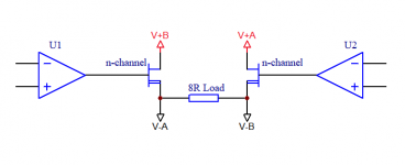
Circlotron, interesting. If I understand correctly (see attached sketch) - VA and VB are two isolated supplies lets say. For one half cycle current flows from V+B through load (speaker) to V-B. On the opposite half cycle current flows from V+A through the load to V-A.
I'm assuming feedback loop here. Advantage no hard to control bias current (DC offset) across the load. Disadvantage - where voltage across the load should be (and is) 0V two currents can flow simultaneously essentially drawing power from VA and VB supplies.
Both Mosfets remain hard to control. Control is achieved because they are fighting each other (in the feedback loop).
Attachments
To make a series regulator you need a device that performs well at low dropout voltage (high transconductance and low capacitance). And at low dropout voltage, FET capacitance increases dramatically. So BJTs have an advantage for regulators.
The output stage of an amp is a different story.
Yes and as the Linear Regulator gets hotter the Mosfet turn on threshold drops and adds to the stability problem.
Yes and as the Linear Regulator gets hotter the Mosfet turn on threshold drops and adds to the stability problem.
Threshold voltage has nothing to do with loop stability.
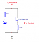
Stability of this circuit depends on input cap, output cap, parasitic inductance, and transconductance of the FET, but not threshold voltage... Although since there is no feedback the output voltage will fluctuate with temperature which may not be practical...
Amplifying Devices And Low Pass Amplifier Design ( 1968)
Charge controlled. ALL of them: FETs vacuum or crystal, also BJTs.
Amplifying Devices And Low Pass Amplifier Design (1968), Edward Cherry and Hooper
But BJT leak a lot more than anything except an over-whipped tube.
.... Barrie Gilber{t}, "The Current-Mode Muddle":
"The BJT is ...... a voltage-controlled current source.
Charge controlled. ALL of them: FETs vacuum or crystal, also BJTs.
Amplifying Devices And Low Pass Amplifier Design (1968), Edward Cherry and Hooper
But BJT leak a lot more than anything except an over-whipped tube.
- Home
- Amplifiers
- Solid State
- bi polar transistors vs mosfet