djk said:The LM318 can slew at 70V/µS, the Jung criterea for slewing induced distortion is a minimum of 0.5V/µS per peak volt of output.
That would mean only a 40V/µS slew rate would be adequate (for the 80V rails).
This is true only of single pole miller compensated designs.
If it is not single dominating pole then it is a oscillator.
Slew rate of a BGW op amp is uninteresting, since the
OP output swing is less than 1V at full output swing.
Therefore virtually any OP has speed enough for this
application. But that doesn't matter these amps sounds
like a POS. Let them be buried together with other unpleasanties
of the 60's and 70's.
OK OK I know there are ways of reaching stability with more poles
with a lot of tricks, in schematics and Spice but this is the real world
where there is spread of component values, stray caps etc.
Andreas Wahlberg
Andreas W said:If it is not single dominating pole then it is a oscillator.
Andreas Wahlberg
No.
What matters is that a single pole roll-off is maintained at unity loop-gain.
Before this, you can have a double-pole roll-off without any instability.
Completely correct, but how do you maintain that under ALL circumstances. Especially in a construction like BGW where the gain stage, the emitter grounded amplifiers load are a fraction of the amps loading. That load you don't know anything about, that is one dimension. THe other dimension is spread of parameters of components and stray caps in the cirquit. You end up with a two dimensional problem, ie you can't sweep every possibility there is, and in some area you could have a 180degree at one gain, ie oscillations.
I myself have toasted a few speaker components on the altar of bandwith, but not anymore. For me it's 90degree all the way to -10dB gain or more.
Andreas Wahlberg
I myself have toasted a few speaker components on the altar of bandwith, but not anymore. For me it's 90degree all the way to -10dB gain or more.
Andreas Wahlberg
Andreas W said:Completely correct, but how do you maintain that under ALL circumstances.
Andreas Wahlberg
Easy: use double-pole compensation.
Hi guys, i have a BGW 750C with a now a broken gain control.
anybody here knows what brand, type, and where to get it?
its a 22K ohm pot with 22 positions( am i right about this?).
any help would be appreciated 🙂
anybody here knows what brand, type, and where to get it?
its a 22K ohm pot with 22 positions( am i right about this?).
any help would be appreciated 🙂
bgw750 manual
I had one somewhere but i cant seem to locate it.
i found my manual for the 100 the baby brother version
(similar topology much lower power)
and i still have a 750 and a 100 amp colecting dust
I had one somewhere but i cant seem to locate it.
i found my manual for the 100 the baby brother version
(similar topology much lower power)
and i still have a 750 and a 100 amp colecting dust
oops forgot
all the 750s i worked on had a bourns pot
the square blue ones no clicks
they did seem to break often
not very helpfull but something to go on
all the 750s i worked on had a bourns pot
the square blue ones no clicks
they did seem to break often
not very helpfull but something to go on
bgw750
Thanks for the tips. By now, I've fixed nearly any problem in my bgw750, but there is still a DC-offset with +13V. Today I've changed all caps, but there is no change. Afterwards I solderd out the second Resistor next to T340, and the dc-offset went to 18Volts. The original resistor has got 10kohm. I think, if I change to 7 or 6 kohm, the Offset will be gone. But...is this usual?
Torsten
Sorry about my bad english...
djk said:If the 2.2uF fit, they're fine. I usually use between 0.1uF~1uF due to space limitations. I find that anything is a big improvement in sound.
Thanks for the tips. By now, I've fixed nearly any problem in my bgw750, but there is still a DC-offset with +13V. Today I've changed all caps, but there is no change. Afterwards I solderd out the second Resistor next to T340, and the dc-offset went to 18Volts. The original resistor has got 10kohm. I think, if I change to 7 or 6 kohm, the Offset will be gone. But...is this usual?
Torsten
Sorry about my bad english...
thanks amp-guy! at least, now i know the brand. maybe will just look for a near replacement, if not exact...
@djk
am not so of a technical guy, am not very good at reading schematics too. but am interested about putting these capacitors...
so i have some questions:
1) will these mylar polypropylene caps do? http://cgi.ebay.ca/MYLAR-Metallized...ryZ14977QQssPageNameZWDVWQQrdZ1QQcmdZViewItem
2) where exactly is this "signal path" i need to solder it on to? will it be on the amp modules, or somewhere near the octal sockets or input connectors?
and lastly, i couldn't find any 47uF polypropylenes.... or am i getting it wrong? the most i have seen is a 4.7 µF...
i saw a Japanese site that moded a 750C, and in the pictures, there is this mod that the repair guy installed 2.2µF polypropylene across the big electroliytics. i guess this one messed my thoughts all up...
please shed some light 🙂
http://images.google.ca/imgres?imgu...ev=/images?q=bgw+750&svnum=10&um=1&hl=en&sa=N
djk said:If the 2.2uF fit, they're fine. I usually use between 0.1uF~1uF due to space limitations. I find that anything is a big improvement in sound.
@djk
am not so of a technical guy, am not very good at reading schematics too. but am interested about putting these capacitors...
so i have some questions:
1) will these mylar polypropylene caps do? http://cgi.ebay.ca/MYLAR-Metallized...ryZ14977QQssPageNameZWDVWQQrdZ1QQcmdZViewItem
2) where exactly is this "signal path" i need to solder it on to? will it be on the amp modules, or somewhere near the octal sockets or input connectors?
I don't go overboard with the caps, Panasonic electrolytics with small polypropylene bypass tacked in parallel are what I use. There isn't much room for big film&foil types anyway. I do use a pair of 47µF across the main supply filters, this really affects how the bass sounds. In general, the caps I replace and add cost about $4 for the lot.
and lastly, i couldn't find any 47uF polypropylenes.... or am i getting it wrong? the most i have seen is a 4.7 µF...
i saw a Japanese site that moded a 750C, and in the pictures, there is this mod that the repair guy installed 2.2µF polypropylene across the big electroliytics. i guess this one messed my thoughts all up...
please shed some light 🙂
http://images.google.ca/imgres?imgu...ev=/images?q=bgw+750&svnum=10&um=1&hl=en&sa=N
"and lastly, i couldn't find any 47uF polypropylenes.... or am i getting it wrong? the most i have seen is a 4.7 µF...
i saw a Japanese site that moded a 750C, and in the pictures, there is this mod that the repair guy installed 2.2µF polypropylene across the big electroliytics. i guess this one messed my thoughts all up..."
Solen sells some 200µF polypropylene that I have used before, but they are huge and expensive, that's why I said I use electrolytics across the main filter caps and it's called 'the $4 mod'.
The mylar caps you linked to look way too big to go in the circuit board. You can buy small 50V polypropylene caps for a few pennies anyway, why bother with eBay.
"I am not so of a technical guy, am not very good at reading schematics too. but am interested about putting these capacitors...
2) where exactly is this "signal path" i need to solder it on to? will it be on the amp modules, or somewhere near the octal sockets or input connectors?"
Obtain the schematic and post it. I will mark the parts for you. If you can get the board layout I will locate the parts for you. If you cannot do this you will need a (competent) local technician to do the job for you, and not a general electronics/TV type person.
Hi djk,
-Chris
I'll back you up on that comment!If you cannot do this you will need a (competent) local technician to do the job for you, and not a general electronics/TV type person.
-Chris
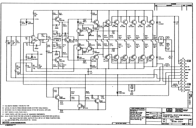
http://i56.photobucket.com/albums/g196/dkleitsch/bgw750c_path.jpg
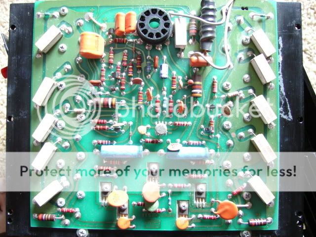
http://i56.photobucket.com/albums/g196/dkleitsch/DSC02421.jpg
Orange is input signal path, green is feedback path.
C1 and C3 make the biggest difference in clarity, C11 and C12 a smaller one (because they have a DC bias). I tack bypass caps across all of these.
Putting a pair of 47µF across the main filter caps on the chassis makes a big difference in how the bass sounds (observe polarity).
The next step is to replace all the little yellow ceramic discs with silver mica or polypropylene (as size dictates), and the orange
Mylar with polypropylene. I don't generally do this last paragraph, but it is an improvement.
I do the $4 mod (C1, C3, and the 47µF pair) on most amps and then stop. It gives the biggest bang for the smallest amount of money and time invested.
Clean the jacks and sockets with De-Oxit and resolder all the sockets for the outputs if they look grey (old solder must be wicked off first).
thanks a million djk!!!
i gues i will be busy this whole week for this 😀
------------------"to the bat cave!!!"------------------
i gues i will be busy this whole week for this 😀
------------------"to the bat cave!!!"------------------
hello Andreas
I have interest at your Amp. Please send me more information.
many thanks 😀
best regards Holger
No no no, it is not constant, thenit wouldn't be a novelty.
The lower cirquit maintains at least ca 1V over the diodes at all time, thereby the upper transistor controls the output at all times, ie class A.
The resistor in parallel to the diodes is 10R ca, giving a Iquiscent of ca100mA, no unneccesary heat. Bingo, no heat and class-A.
I have built about 10 of these, and they sell for $2000. Most customers listen two songs, ask the price and buy, nice people.
Andreas
I have picked up yet another 750
Of course 1 channel was blown However a replacement set of output devices has restored full operation
As to my first BGW I have at last located a LM318 metal can IC that I have fitted so all is well
What an amplifier not the best or worse sounding I have heard but built like a truck and very easy to service
The main reason I have added this is to say that I have been caught out by the fake MJ15024/5
I am not sure where they came from as I am always buying devices having cut open a fake I am stunned at the depths that some people will go to as well as stealing my money thay are also stealing my time
regards Trev
I still have a couple of hundred eBay MJ15025 I'll make you a sweet deal on.
I will now only buy in 100 lot from authorized ON Semiconductor distributors.
It's becoming a real problem, when even people you should trust (MCM/Newark/Farnell) are selling fakes.
I will now only buy in 100 lot from authorized ON Semiconductor distributors.
It's becoming a real problem, when even people you should trust (MCM/Newark/Farnell) are selling fakes.
If you replace LM318 with NE5534 its another amp, its a big difference.... 750B is sounding clear like todays amps
Test it
Test it
- Home
- Amplifiers
- Solid State
- BGW 750B output modules