Hi Marc
If you do not mind to post your layout that would be great.
Better to use (have) some SMD parts on the layout than no layout at all.
Thank you
Look like I got 10pair FAKE Hitachi to.
I do have a pair NOS original so I can clearly see the difference between them.
Greetings G
If you do not mind to post your layout that would be great.
Better to use (have) some SMD parts on the layout than no layout at all.
Thank you
Look like I got 10pair FAKE Hitachi to.
I do have a pair NOS original so I can clearly see the difference between them.
Greetings G
If you want : I have classical layout (output at the end of the board), one with output at ech side of the board and to version 2 output pair (to3p and to264 device)....wich will interest you. The SMD allows my to have more room for MicaAg caps and bigger decoupling caps as using 6.3mm faston sapd...
Marc
Marc
Marc
One pair power trans. will be good enough I think.
Thank you
Greetings Gabor
Here if it's fit to you...
Don"t Know what happened......Diyaudio refused strictly to upload : "BG3mg_sch.jpg:
Upload of file failed. "
Marc
Upload of file failed. "
Marc
That is bad.
Probably the size was too big, other than that hard to imagine.
Did you tried the color with the parts what U used to post?
That would be more than good enough for me, anyway lets see until someone will test it or Borys will give a green light to the final schematic.
Greetings Gabor
Probably the size was too big, other than that hard to imagine.
Did you tried the color with the parts what U used to post?
That would be more than good enough for me, anyway lets see until someone will test it or Borys will give a green light to the final schematic.
Greetings Gabor
That is bad.
Probably the size was too big, other than that hard to imagine.
Did you tried the color with the parts what U used to post?
That would be more than good enough for me, anyway lets see until someone will test it or Borys will give a green light to the final schematic.
Greetings Gabor
I made as usual...it's not the first time i attached a files....they don't weight more than 60ko....send me your mail through email, i follow you files...
Marc
I have problem with upload too.
At the moment version v5.1 is playing in my house.
Gabor send me pm with email (I can not find your email, prapobly lost it) and I will send you schematic 5.1. Some tweeks may be required If there will be a problem with temperature (but schould be ok)
At the moment version v5.1 is playing in my house.
Gabor send me pm with email (I can not find your email, prapobly lost it) and I will send you schematic 5.1. Some tweeks may be required If there will be a problem with temperature (but schould be ok)
I have problem with upload too.
At the moment version v5.1 is playing in my house.
Gabor send me pm with email (I can not find your email, prapobly lost it) and I will send you schematic 5.1. Some tweeks may be required If there will be a problem with temperature (but schould be ok)
Hi borys,
Could you send me the schematic too?
Marc
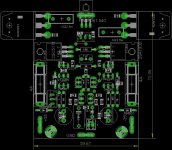
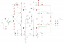
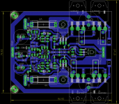
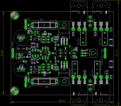
Here are layout we talk about, i attached 2 pairs version too.
Marc
Marc
Attachments
-
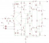 BG3mg_sch.jpg78.9 KB · Views: 499
 -
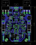 BG3mg_brd1.JPG58.1 KB · Views: 480
 -
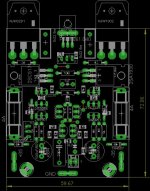 BG3mg_brd2.JPG54.5 KB · Views: 463
 -
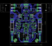 BG3mgv2_brd1.jpg59.2 KB · Views: 435
 -
 BG3mgv2_brd2.jpg55.1 KB · Views: 432
 -
 BG3 v5.1mg_v2_100_to3p_sch.png28.3 KB · Views: 341
 -
 BG3 v5.1mg_v2_100_to3p_brd1.png48.7 KB · Views: 338
 -
 BG3 v5.1mg_v2_100_to3p_brd2.png34.9 KB · Views: 255
Here are layout we talk about, i attached 2 pairs version too.
Marc
Have you tried the proto. before making pcb-s, you can`t compensate temp of a triple with a simple Vbe multiplier...
Last edited:
By any chance someone built these amp.
Tomorrow I go for laser printing, it would be good to know which one to build.
These or the BG-1.???
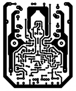
Any way I made the lay out after Marc design (thank you Marc🙂) using regular resisters, I do post it if someone interested.
To get the right size you must set up your printer to 85%.
I do not have silkscreen for these but I can help, also if you look at Mark lay out with the two pair power transistors these lay out born out of that.😀
Only mode I made I have some nice Philips Axial 1000uF 100V caps and I want to test those to next to the power BJT..
Greetings Gabor
Tomorrow I go for laser printing, it would be good to know which one to build.
These or the BG-1.???
Any way I made the lay out after Marc design (thank you Marc🙂) using regular resisters, I do post it if someone interested.
To get the right size you must set up your printer to 85%.
I do not have silkscreen for these but I can help, also if you look at Mark lay out with the two pair power transistors these lay out born out of that.😀
Only mode I made I have some nice Philips Axial 1000uF 100V caps and I want to test those to next to the power BJT..
Greetings Gabor
Attachments
Hi borys, that is a very good design! I use ON semi output devices - MJL321A NPN and MJL1302A PNP 200 Watt transistors which are very good output devices.
- Status
- Not open for further replies.
- Home
- Amplifiers
- Solid State
- BG3 - diamond amp - simple