What horn/voltage input is that?
BTW my opinion on the BFM subwoofers is that the V-Plate should be treated as part of the horn ESPECIALLY with the 'box' Tuba cabs. I think the reason the T36 got decommissioned is because it is such a big cab that not everyone has the room for 2 and a V-Plate, whereas the T60 and Titans will work better alone, .
Uh... no.
I can fill you in on the details on that one. A builder (not BF himself) built the T36, BF had just drawn up the plans only. The builder built it, and measured it INDOORS... I repeat INDOORS. BF, never measured it, never built it -- took it all as gospel, and published on his site for THREE YEARS. When customers couldn't reproduce the results expected, it was, "you got a leak, you did it wrong, you didn't follow the plans."
It wasn't till I built them, measured them over and over -- and the guilty party that measured them indoors fessed up.
For the expected reasons -- all those posts got deleted from BF's forum.
"link? "
Lazy?
JBL MPro MP415
http://www.jblpro.com/pub/mi/MP415.pdf
Multiple drivers will couple if withing 1/4W of the highest frequency of interest.
The limit on coupling is reached at about No=25%, where as a FLH could hit 50%
Lazy?
JBL MPro MP415
http://www.jblpro.com/pub/mi/MP415.pdf
Multiple drivers will couple if withing 1/4W of the highest frequency of interest.
The limit on coupling is reached at about No=25%, where as a FLH could hit 50%
Last edited:
Not trying to be lazy. you cited a paper your presumably had read. all i asked for was source.
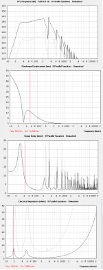
Alright. Googled. This doesnt appear to be relevant. I was not referencing going from whole space to half space and the gains in low frequencies we see from that (this is a given, in whole space the nearly omnidirectional frequencies receive no positive reinforcment from reflected waves as we see in 2pi/1pi/.5pi). I was addressing the fact that using the "multiple speakers" option in hornresp results in a reduced Low corner and increase in output near low corner with all designs, when in fact it should not.
This is clearly shown by the picture I've attached, which demonstrates a shift in group delay, and impedance following use of the multiple speakers utility.
Attachments
Last edited:
In hornresp, I have modelled multiple vented enclosures and corner loading. I have found the system tuning lowers but the displacement peak shifts down the frequency band and actually increases slightly.
I'd assume this is because the increased air load on the driver acts to increase Mms and lower Fs. Also the air in front of the ports would increase their effective length. With corner loading the front loaded and tapped horns I've modelled, corner loading REDUCES the displacement peaks, so there is that advantage to the horn cab. As for Bill Fitzmaurice, he wouldn't specify a higher voltage limit that would risk the driver bottoming out as the cab was moved out of the corner!!
With horn cabs that have a rising response, the upper bass is closer to the efficiency maximum than the lower bass, thus putting them in groups will give a higher potential for bass boost. What happens is the upper bass is boosted by 6-8dB (space concentration of the corner) and the lower bass by 12dB (6dB space concentration and 6dB increased pressure resistance). When you get close to the efficiency maximum, the displacement of the cone simply drops in response to the added air load.
With a big wall of horns, you may induce a 'phantom air column' in front of the stack, so you could lower your cut off.
With an inefficient vented enclosure ('Heavy' woofer in a small box such as in car audio) or almost any 'home theatre in a box' bass bin, the change in air load is negligible, therefore you wouldn't notice as much difference in response.
Please note that this comment is just my analysed thoughts on the matter and has not been confirmed through real world analysis.
Mutual coupling is caused by the pressure wave from 1 speaker exerting pressure on another cone. If that cone is also moving in phase, then the other speaker will push against this back pressure, thus compressing the air more than it could otherwise.
The perfect 6dB boost can only be had in all directions with:
Perfect phase; No reduction in cone displacement from the back pressure
The higher the bass note, the harder it is to be in phase with 1/4 wavelength apart providing only a 3dB boost from the side of the stack. The farther away the subwoofers are, the less pressure they can exert on each others' cones, so the boost is limited to a 'power alley' where both are in phase. With a stack of woofers, you'd have better midbass on axis than out to the sides.
Note that on axis, the summation can happen up to quite high frequencies, which is why 4 x 12 guitar cabs are so loud when pointed at you!
JBell I remember you posting a graph actually which was at over 100dB until 40Hz. It doesn't add up with the new Tubas (30 and 24) which are down in the lower 90s for the lower bass, unless V-Plated in pairs. At a guess, I'd expect the Tuba 36 to be down about 95dB to the upper 20s, rising into the 100s past 60-70Hz.
The only cab that has the response you were after (maximum sensitivity above 40Hz) is the WIDE (30+ inches) Titan 48. (unless that was measured indoors too 😉 ) INDOORS you'd have all sorts of cabin gain. So I do think that was unprofessional on Bill's part.
I said about it on the forum, but someone else piped in (NOT BILL), this is supposed to be about Bill's designs. Then Bill said yeah, OT Posts deleted. Since then that thread turned into a one about who has had the biggest electric shock and Bill didn't delete those comments!
funny you bring up the T48....
after exposing the T36, I asked about this T48 graph... and promptly got all of my posts deleted.......
Which one of these... is not like the other....
http://billfitzmaurice.net/images/SPL/T48/8cabs.gif
http://www.prosoundshootout.com/Measurements/2007/Titan100w.jpg
Oh, and the T36's I built, were 36" wide.....
Last edited:
Well I'm not sure what width or driver is being used there. (If it's an 18 inch cab with a Delta 15LF that would explain it) I assumed the BFM graph was for 24 inch wide cabs in parallel with a 3015lf. I asked Bill about graphs (for Tuba 24) and he said that multiples were ESTIMATED based on that of one, so not all measured.
I assumed the Titan graphs were correct as the larger effective mouth would mean less dip in response. Those shootout graphs do show quite a big drop though. Oh well I've got the plans, I could build them for myself when I have the room.
No matter how wide you build the Tubas they are always going to dip as I believe they were designed around the V-Plate in order to save on size. I believe the graphs in my T30 plans to be reasonably accurate, but not that impressive down low (30 inch wide only 95dB efficient from 30 to 50Hz e.g. more LOWER bass from a smaller vented box) and also some of the advertising statements on the site were, to quote Paul Klipsch, "********"
Having said that I'm pretty happy with the OT12s I built, although I needed to tame the aggressive mids of the compression driver by 10dB to get them to sound at their best. I was using Beyma cd10fe. Stacks of headroom on them though there isn't as much output at the crossover region as higher up (could be part cancellation though as they were 2' from the corner of my room)
I didn't much like certain aspects of the forum. Too many "White Knight" cabinet builders.. I'm a bit more of a tech head and like to discuss different designs without being accused of 'Mental Masturbation' by a New Zealand guy with a BFM designed motorcycle (lots of noise and not much power).
Bill's subwoofer placement advice is GOLD though. I believe users putting their subs in a BETTER PLACE can make more difference than any design.
P.S. You'd have to put at the end of the message on BFM: Watch this post.. if it's not here in a few days - conspiracy! 😉
OT12's aren't bad... in fact I still build a horn loaded top that could be accused of being similar. The side handle port "feed back generators" just are unacceptable to me. There is a very good place for ports in a horn loaded cabinet, just think synergy....
However on the subs, and specifically the T39 which was the original posters question...
All BFM tuba/titan's are essentially designed the same. -13db@40hz vs 100hz. No reactance annulling -- that is just BF's design goal. I don't happen to agree with it.
Here is my comparison.
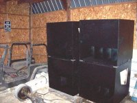
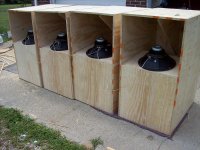
36" T36, 27cu.ft. 95db@40hz@28v/10m
StadiumHorn, 20cu.ft, 102db@40hz@28v/10m
WITH THE EXACT SAME DRIVER... aka, the exact driver was pulled from one cabinet and put in the other. same testing hardware, an apples for apples comparison.
Lets just say the T39 isn't a monster sub either... the SS15 beats it easily.
However on the subs, and specifically the T39 which was the original posters question...
All BFM tuba/titan's are essentially designed the same. -13db@40hz vs 100hz. No reactance annulling -- that is just BF's design goal. I don't happen to agree with it.
Here is my comparison.
36" T36, 27cu.ft. 95db@40hz@28v/10m
StadiumHorn, 20cu.ft, 102db@40hz@28v/10m
WITH THE EXACT SAME DRIVER... aka, the exact driver was pulled from one cabinet and put in the other. same testing hardware, an apples for apples comparison.
Lets just say the T39 isn't a monster sub either... the SS15 beats it easily.
Attachments
Funny you should mention the ports in the mouth. I asked about that on the forum, someone posted a quote from Bill saying it would mess up the response. (I knew putting them too far in may cause problems, I wanted to put them as far out as they would go).
I just end up following the plans, centering them on the sides. They would have been blocked with pillow stuffing in the mouth anyway. They make good handles, and I'm planning on mostly recorded music through them, not live sound. Blocking the ports altogether would result in increased displacement around the crossover region - more distortion and less headroom, though I was using drivers with 6mm Xmax (3012HO). By eye and a sine wave sweep, I found the displacement peak was at around 120Hz.
The Titan 36" wide Titan 48 has less dip, and is 102dB at 40Hz with more up top.
 You can of course question if it was measured outside too if you wish 😀. Such a chart from a Tuba 36 (designed for extension to 28Hz, and to be cross firing/V coupled for the correct mouth flare) would make me suspicious, but a shorter horn and larger mouth from the Titan which (would be a 24 cu ft cab!) made me think legit graph. I mean Bill doesn't even try to hide the low sensitivity region of the Tubas anymore:

The V-Plated graphs look more impressive though there's NO WAY I'd use an S2010 as a subwoofer driver
 , that coming from someone who was blocked from BFM facebook group for saying a Kappa 12 THAT THE GUY ALREADY HAD AND DIDN'T HAVE TO WASTE MONEY ON!!!! would work quite well in an OT12 (rising response, only 3mm Xmax, QTS a tiny bit lower than recommended).
I'd expect your 'Stadium horn' (which was smaller than I thought at 20 cubic feet) cab to beat the equivalent 30" T48 at low bass though, with less upper bass. What is the voltage limit on the Stadium Horns? I think it's 60V on the Titan and I've gotten 48V with a simple BR design in the same range. Also, have you experimented with 'V-Coupling' the Stadium Horns? I read the thread a while back but it was too old to write anything on. Not that this thread is that new either but I haven't found any 2014 ones on this topic.
There is a maximum sensitivity above 40Hz version of the T48, and extended response option (largest rear chamber).
As for the 'rising response' philosophy, I'm not sure why the latest Simplexx design bass reflexes have it. In horn-resp, I have designed bass reflexes to be a bit louder at tuning frequency to make the most of 'displacement headroom'.
I'm hoping it's not some 'driver stability' thing that stops a driver wavering around at high power, where the coils of mine will risk striking the back plate even within high pass and displacement limits!!
I just end up following the plans, centering them on the sides. They would have been blocked with pillow stuffing in the mouth anyway. They make good handles, and I'm planning on mostly recorded music through them, not live sound. Blocking the ports altogether would result in increased displacement around the crossover region - more distortion and less headroom, though I was using drivers with 6mm Xmax (3012HO). By eye and a sine wave sweep, I found the displacement peak was at around 120Hz.
The Titan 36" wide Titan 48 has less dip, and is 102dB at 40Hz with more up top.
The V-Plated graphs look more impressive though there's NO WAY I'd use an S2010 as a subwoofer driver
I'd expect your 'Stadium horn' (which was smaller than I thought at 20 cubic feet) cab to beat the equivalent 30" T48 at low bass though, with less upper bass. What is the voltage limit on the Stadium Horns? I think it's 60V on the Titan and I've gotten 48V with a simple BR design in the same range. Also, have you experimented with 'V-Coupling' the Stadium Horns? I read the thread a while back but it was too old to write anything on. Not that this thread is that new either but I haven't found any 2014 ones on this topic.
There is a maximum sensitivity above 40Hz version of the T48, and extended response option (largest rear chamber).
As for the 'rising response' philosophy, I'm not sure why the latest Simplexx design bass reflexes have it. In horn-resp, I have designed bass reflexes to be a bit louder at tuning frequency to make the most of 'displacement headroom'.
I'm hoping it's not some 'driver stability' thing that stops a driver wavering around at high power, where the coils of mine will risk striking the back plate even within high pass and displacement limits!!
Last edited:
Tim,Funny you should mention the ports in the mouth. I asked about that on the forum, someone posted a quote from Bill saying it would mess up the response. (I knew putting them too far in may cause problems, I wanted to put them as far out as they would go).
By eye and a sine wave sweep, I found the displacement peak was at around 120Hz.
Fb (excursion minima) is usually about 1/3 octave below the upper excursion maxima, with a 120 Hz maxima, Fb is probably in the 95 Hz range.
The wavelength of 95 Hz is around 12 feet long, placement of the port which has omnidirectional output does have ramifications, though in a small cabinet makes little difference unless physically close to the port output.
In the case of a measurement (or vocal) mic 1 foot away from the port, compared to one two feet away- the port output of the second would be -6 dB compared to the first. As in most of BFM's designs, they are not aimed at live sound reinforcement, where small details like port placement can have large ramifications.
When porting long horn loaded cabinets, the phase inverted port output needs to be in phase with the output of the horn in the octave (or so) of the port output region, so placement becomes critical, or it may indeed "mess up the response".
Hornresp does give an option for the distance to the port relative to the horn output, though that does not address placement of the port well within the horn path, which adds another layer of complexity that is not currently addressed in the software.
Art
- Status
- Not open for further replies.
- Home
- Loudspeakers
- Subwoofers
- BFM Titan 39