The #84 was a link in previous post, but click here to see the schematics.Why?
What does it do to improve performance? What effect does it have on output capability? What does it do to device parameters that vary with temperature?
Schematic of what you have done would help us understand.
As I was using too small heatsinks on IRF610 it warmed up to 50C after 10mins, so I decided to consume 18mA with a res, so the IRF610 has to drop less, ~20mA (so no voodoo here)
Please consider that I'm using the preamp from post #234
Last edited:
if either of the 610s were running too hot then it would be better, in your installation to increase the 3r3 resistor to reduce the CCS current and thus reduce the heat that needs to be dissipated.
Ask and you will get the information. Guess and you may guess wrongly.
Ask and you will get the information. Guess and you may guess wrongly.
vzs, strong hum with shunt reg and clear 100Hz peak with battery are indicators of bad grounding scheme. Work your wires to avoid ground loops 😉
I asked this and Juma responed 😉 "R1 of 12R gives you CCS current of about 50ma - don't increase the value of that resistor (15R max.)"if either of the 610s were running too hot then it would be better, in your installation to increase the 3r3 resistor to reduce the CCS current and thus reduce the heat that needs to be dissipated.
Ask and you will get the information. Guess and you may guess wrongly.
I also wrote that I'm using 12R not 3R3, so the CCS supplies ~55mA
I don't think that this has anything to do with the 100Hz hum I measure and hear anyway.
Presumably Juma answered the question you asked.I asked this and Juma responed 😉 "R1 of 12R gives you CCS current of about 50ma - don't increase the value of that resistor (15R max.)"
I also wrote that I'm using 12R not 3R3, so the CCS supplies ~55mA
Did you tell him that you intended to fit 610 heatsinks that are too small and ask what he would recommend for your installation?
You must ask the right question.
Yes I did...Vzs, did you check the post #237 ?
I'm using the recommended PCB and 🙄 I think the main design goal was to use every tenth of a millimeter from the board (I will post photo tonight), so it's very cramped and simply a bigger heatsink cannot be fit. I could, somehow, use some L profiles and dissipate the heat above the reg but I didn't had time for these tricks.
I could remove the 1.56K, no prob, and test only for 10-15mins. As I'm not using the buffer part from output I thought to consume approx that much with something else...
I will post my wiring scheme right away... as I suspect bad grounding as well.
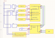
This is how the grounding is done. I might connect the Preamp ground to the DAC ground directly, not only through the connecting wire. What do you think?vzs, strong hum with shunt reg and clear 100Hz peak with battery are indicators of bad grounding scheme. Work your wires to avoid ground loops 😉
later edit: small correction
Attachments
Last edited:
Try to rearrange the wires into single star ground scheme with a ferrite bead in ground line coming from digital part of the DAC. Especially take care about PSU ground lines - transformers are probably OK since 100Hz hum is dominant.
In the quest of finding the 100Hz hum I started by disconnecting everything from the preamp and tried these:
1. floating input (only 1M to GND), loud hum only now it's like an antenna, if I close my hands to the jfets its starts humming louder
2. connect input to ground - no hum, silent
3. connect input to ground through 2K - similar to 1, so remove it
4. use battery and disconnect negative AC - no hum, I wish I have this with negative PSU 🙂
5. use battery + connect negative AC back _but do not connect the negative reg to jfets_ - same hum as before 😕
I measured the negative reg: raw DC 10.5V, output DC set to 5.8V, after 2 leds I have 1.55V, it draws 45mA, Vgs of Fets are 3.95V and 4V. Seems to work in parameters.
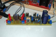
As you can see from the attached pics I used the PCB from this thread.
1. floating input (only 1M to GND), loud hum only now it's like an antenna, if I close my hands to the jfets its starts humming louder
2. connect input to ground - no hum, silent
3. connect input to ground through 2K - similar to 1, so remove it
4. use battery and disconnect negative AC - no hum, I wish I have this with negative PSU 🙂
5. use battery + connect negative AC back _but do not connect the negative reg to jfets_ - same hum as before 😕
I measured the negative reg: raw DC 10.5V, output DC set to 5.8V, after 2 leds I have 1.55V, it draws 45mA, Vgs of Fets are 3.95V and 4V. Seems to work in parameters.
As you can see from the attached pics I used the PCB from this thread.
Attachments
Last edited:
Obviously there's a ground loop that affects the -V supply. Chasing it is the only way to go - try different ground connections between DAC and preamp, dividing signal and power ground. When you find the solution analyze the ground path so that doesn't happen again 🙂
BTW, that heatsink on the shunt reg is really too small...
BTW, that heatsink on the shunt reg is really too small...
If you are using the scheme shown in post #234, i see that input ground and preamp ground are separated. They must be connected at one common point.
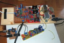
They are connected to a common ground, here you can see the actual PCBIf you are using the scheme shown in post #234, i see that input ground and preamp ground are separated. They must be connected at one common point.
Juma, for the last version of your 6dB circuit, (I think it is post #23), what is the typical distortion level for 2V in 4V out?
Thank you.
Thank you.
I don't do that kind of measurements - if piano reproduced sounds like piano live and if same goes for medium size acoustic orchestra - I'm fine with that, no additional measurements needed 😉
I don't know where you live and what possibilities are open to you, but I tend to visit acoustic concerts often and that's my reference point - natural sound of instruments and voices, live, with no amplification.
I don't know where you live and what possibilities are open to you, but I tend to visit acoustic concerts often and that's my reference point - natural sound of instruments and voices, live, with no amplification.
I substitute a different test.Juma, for the last version of your 6dB circuit, (I think it is post #23), what is the typical distortion level for 2V in 4V out?
Can the pre-amp pass a +10dB signal without clipping, ref the maximum input signal of the power amp?
This then puts the maximum preamp music signal @ -10dB ref clipping.
My target is actually 20dB of overhead, i.e. the maximum pre-amp audio signal is just 10% of the clipping level. This gets the distortion quite low for most ClassA circuits.
using the power supply for J 310 pre
I want to build the power supply posted in No 28 of this thread.
I want to use the power supply for the J310 pre posted by JUMA in the JFET BOZ thread.
Queries:1) Is the value of C14 and c 17 critical? Is 3300UF and 470 UF OK ?
2) Is the quality of the cap important ?
3) To get dc 24 V out, the input ac is 24 V ?
thanks
kp93300
1.) you can choose any value of C14 and C17 in range.
3.) Input ac is 24Vac and 9Vac
i wish to hear about the question 2.) too 🙂)
3.) Input ac is 24Vac and 9Vac
i wish to hear about the question 2.) too 🙂)
...Queries:
1) Is the value of C14 and c 17 critical? Is 3300UF and 470 UF OK ?
2) Is the quality of the cap important ?
3) To get dc 24 V out, the input ac is 24 V ?
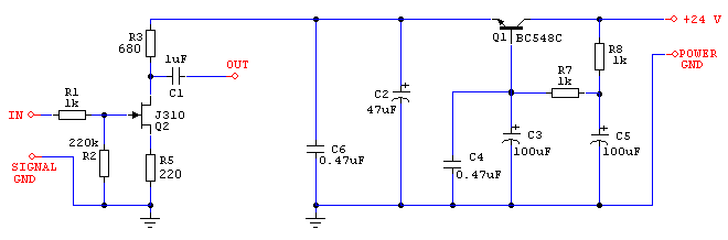
I suppose you are talking about this preamp (disregard the cap. multiplier). If that's so, you should know this too.
Answers:
1) C14 can be anything from 47uF to 470uF and C17 is "the bigger, the better" type.
2) Use good parts from reliable suppliers, but don't waste your money on "Le Boutique Audiophile" nonsense. The value of the coupling cap (C1 in preamp sch.) should be adjusted according to Zin of the following stage - 10uF will cover you down to 10k. Wima MKP 10 or Siemens stacked foil is what I use in that position.
c) yes, 24V AC will do the job. If you go higher than that Q11 will need a bigger heatsink.
Last edited:
- Home
- Amplifiers
- Pass Labs
- BF862 Preamp