Since I want to have an input selector (relay based), I am inclined to go with the buffer as the first stage, followed by volume pot and then the gain stage, which should have a sufficiently low output impedance to drive the interconnect to the power amp.
I did not miss your underlying point.Hi Andrew, you missed my underlying point,
I agree with and did not quote the parts of the post that were not controversial.
The problem was the advice you gave and I quoted, about locating a buffer in front of a pot.
no.I want to have an input selector (relay based), I am inclined to go with the buffer as the first stage, followed by volume pot and then the gain stage, which should have a sufficiently low output impedance to drive the interconnect to the power amp.
Gain stage first if some of your sources need it, then pot/attenuator, then buffer to feed the interconnects.
The pot then has the opportunity to attenuate the noise created in the gain stage.
If any of your sources cannot drive the cables and the relay audio pins and the pot then fit a buffer or gain stage at the sources that are incapable.
Then the pre-amp will not need any gain stage, just a buffer.
If the gain stage is guaranteed stable with gains of +0dB, +6dB and +12dB, it would be nice to have a switchable gain stage, for 1times, 2times and 4times. That covers almost every source you are likely to want to connect up.
Last edited:
...the parts of the post that were not controversial.
The problem was the advice you gave...
Controversial? Me?
Problem advice? Me?
Well Andrew you sound like a frustrated engineer in a meeting where he thinks everything must be done his way! Good luck with that!
(And I bet you really want to reply to this post justifying your position...)
I sure don't intend to start a controversy here. Both approached have their merits and compromises. Let's give it a while. I'll come back with what I find out in the practical situation. Thanks again.
Since I want to have an input selector (relay based), I am inclined to go with the buffer as the first stage, followed by volume pot and then the gain stage, which should have a sufficiently low output impedance to drive the interconnect to the power amp.
hate to tread into the muck, but, why not.

I can see reasons for doing it the way you suggest. Not all sources have low output impedance, but are happy driving a reasonable load, i.e. 100-200k. And this load will determine the low frequency cutoff point in combination with the source's output coupling cap, almost always located after the output stage.
It's not always convenient to add a buffer to the output of the source. Especially in a case where a friend may bring over a classic and pricey vintage source made 40 or 50 years ago. This would include reel to real and cassette decks, FM tuners, phono pre-amps, etc.
So why not just use a 100k or 250k pot?
The higher thermal noise related to the higher pot resistance is one reason, probably a minor one.
The pot will have max. output impedance at the midpoint -The output impedance is the parallel combination of R1 and R2, i.e. Zout = (R1 * R2) / (R1 + R2). So for a 250k pot, Zout will be 62.5k, and driving the next stage, a jfet gate.
So what?
Jfets don't like to be driven by high source impedance due to their non-linear input capacitance. This point was discussed in the original B1 thread. The effect can apparently be heard, and certainly measured. So a low value pot, of say, 25K or less is preferred.
Anyway, this leads a logical approach, to me at least, where one may wish to have a line stage with high input impedance R to ground (say 250k), then buffer (b1 type) driving a lowish value volume pot (10 to 25k), which is then followed by either another jfet buffer (b1) or jfet gain stage / buffer.
If one use low gain, and low noise parts (BF862) in the gain stage, noise should not be an issue.
As mentioned, there are many ways to do this. Unless one assigns real world values for components involved, the "do's" and "don'ts" really have little meaning, at least to me. Everything is relative.
Bob
BNFY,
are you aware of the stray capacitances in your system and what effect they could have when they interact with your source and load resistances/impedances?
are you aware of the stray capacitances in your system and what effect they could have when they interact with your source and load resistances/impedances?
BNFY,
are you aware of the stray capacitances in your system and what effect they could have when they interact with your source and load resistances/impedances?
Let's use real values. For you, what is a typical stray capacitance value? Beyond the interconnect cable, where does it come from, and what are typical values?
I usually assume a 1meter twisted cable between the devices, with typical capacitance of 15pf per foot. I'm not building a recording studio, simply connecting a vintage tuner to line stage. The effect of this cable on HF rolloff would be -3dB at at 624kHz using 2k output impedance on the tuner, and 250k input impedance. At 20kHz, it would be -0.07 dB.
Anyway, this leads a logical approach, to me at least, where one may wish to have a line stage with high input impedance R to ground (say 250k), then buffer (b1 type) driving a lowish value volume pot (10 to 25k), which is then followed by either another jfet buffer (b1) or jfet gain stage / buffer.
I think that approach would be logical and sensible for most folks.
cascoded jfet stage is good for all these issues
Good point - the cascode increases bandwidth, and greatly reduces the non-linear capacitance on the jfet input. Going that way may be more efficient than adding an extra buffer in front of the pot for those who need to have a high input impedance.
Only because I must say the obvious, the schematic in post 28 does not include a cascode on top of the gain jfet.
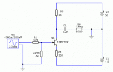
Hi, I'm using the attached schematics (momentarily) as I need 17dB gain. I will try with BF862 as I get my hands on them. Using 16mA IDSS SK170V the THD is ~0.07% (according to the sim) but I will measure it today with RMAA.
I use this preamp after a passive I/V converted AD1865 DAC and I like the sound of the whole very much. I tried it yesterday evening so I'm too biased now 🙂
I have two questions:
1. using the reg schematics from post #84 with R1 = 12R, the shunt mosfet IRF610, even with a small heatsink, is pretty warm after only 5 minutes (I can keep my hand on it but it's warm, ~45-50C). It's feeding only two SK170V biased at 8mA so the consumption is max 20mA.
Should I increase the value of R1 12R or should I use a bigger heatsink?
2. for the negative supply I'm using a 1.5V battery now but I don't want to bother with batteries. Can I set the negative reg to 5.5V and use two 2V leds in series to drop the voltage to 1.5V? Can I try this or I will experience smoke?
Thanks!
Attachments
Vzs,
1. If your input voltage for neg. reg. is 35V (as in sch. in post #84) that's the cause of big thermal dissipation. If so, use a pre-reg. to redistribute the heat (7915 or 7912 or CRC Pi-filter 100uF - 330R/2W - 100uF) before the shunt reg. R1 of 12R gives you CCS current of about 50ma - don't increase the value of that resistor (15R max.)
2. Yes, it will work, just use a nice cap of 1000uF or so after the LEDs. Try different LEDs to achieve exact voltage.
Sorry for misunderstanding... currently only the positive reg is working and with that I have the heat issue. I use 24V AC in, and have ~34V before reg and set 30V after reg. I use 10K multiturn instead of zenner so I can set any voltage. As the consumption is ~20mA probably that dropped 30mA is generating the heat?Vzs,
1. If your input voltage for neg. reg. is 35V (as in sch. in post #84) that's the cause of big thermal dissipation. If so, use a pre-reg. to redistribute the heat (7915 or 7912 or CRC Pi-filter 100uF - 330R/2W - 100uF) before the shunt reg. R1 of 12R gives you CCS current of about 50ma - don't increase the value of that resistor (15R max.)
2. Yes, it will work, just use a nice cap of 1000uF or so after the LEDs. Try different LEDs to achieve exact voltage.
For the negative supply I use 1.5V battery now.
Last edited:
0.9W (30Vx30mA) is nothing to worry about. Use the scope to check for oscillations in the shunt reg. and if everything is fine just put a bit bigger heatsink on the IRF610 and you'll be fine 😉
OTOH, just 4V difference (34V before the reg.) might not be enough for shunt reg to work properly. Try setting the output voltage to 28V. It won't change anything important in the preamp, but it will give some headroom to shunt reg.
OTOH, just 4V difference (34V before the reg.) might not be enough for shunt reg to work properly. Try setting the output voltage to 28V. It won't change anything important in the preamp, but it will give some headroom to shunt reg.
I set the positive output voltage to 28V and added an 1.56K resistor to "eat" 18mA from the IRF610 so now its warm but even after an hour of work is ~45C. Thanks!0.9W (30Vx30mA) is nothing to worry about. Use the scope to check for oscillations in the shunt reg. and if everything is fine just put a bit bigger heatsink on the IRF610 and you'll be fine 😉
OTOH, just 4V difference (34V before the reg.) might not be enough for shunt reg to work properly. Try setting the output voltage to 28V. It won't change anything important in the preamp, but it will give some headroom to shunt reg.
100Hz hum
I have done some listening tests and measurements (RMAA) using for the negative supply either 1.5V alkaline battery or the schematics from #84 (modded for negative as in post #23).
1. 1.5V alkaline battery
Using 1Khz sinus test signal, beside the expected FFT graph I can see a wide peak around 100Hz (-63dB). Strangely this is not audible with my 91.5 dB/m speakers, the whole DAC + preamp + amp is dead silent, but it's clearly visible on the pc-scope.
2. Negative supply set to -1.5V using LEDs (see above)
I didn't measure it because a quiet but clear 100Hz hum can be heard from the speakers. I used 220uF after the LEDs, then I tried 1000uF, but really nothing changed. Beside of this hum the sound is as good as with the battery.
I used 1N5819 in PSU and 4700uF for filtering.
What should I check on both supplies using just a simple V, A meter? Vgs to be ~3V for IRF610 and IRF9610? Steady consumption ~55mA (with 12R for dropping)
What do you suggest?
Thanks!
I'm using the schema from Salas's post #84 for the negative supply as well and I use a 10K multiturn instead of R10 (6K8) so I can precisely set the V out irrespective of LEDs voltage.2. Yes, it will work, just use a nice cap of 1000uF or so after the LEDs. Try different LEDs to achieve exact voltage.
I have done some listening tests and measurements (RMAA) using for the negative supply either 1.5V alkaline battery or the schematics from #84 (modded for negative as in post #23).
1. 1.5V alkaline battery
Using 1Khz sinus test signal, beside the expected FFT graph I can see a wide peak around 100Hz (-63dB). Strangely this is not audible with my 91.5 dB/m speakers, the whole DAC + preamp + amp is dead silent, but it's clearly visible on the pc-scope.
2. Negative supply set to -1.5V using LEDs (see above)
I didn't measure it because a quiet but clear 100Hz hum can be heard from the speakers. I used 220uF after the LEDs, then I tried 1000uF, but really nothing changed. Beside of this hum the sound is as good as with the battery.
I used 1N5819 in PSU and 4700uF for filtering.
What should I check on both supplies using just a simple V, A meter? Vgs to be ~3V for IRF610 and IRF9610? Steady consumption ~55mA (with 12R for dropping)
What do you suggest?
Thanks!
Why?I..... added a 1.56K resistor to "eat" 18mA from the IRF610
What does it do to improve performance? What effect does it have on output capability? What does it do to device parameters that vary with temperature?
Schematic of what you have done would help us understand.
- Home
- Amplifiers
- Pass Labs
- BF862 Preamp