Re: mechanical resistance
If you are asking me there are a dozen or so Lambda's in Poland I would imagine. No problem to ship there. Send me your email as I have those drawings for the 15" and John should have them for the 18"
I have built the exact same driver with both aluminum and Kapton formers and could not tell a difference sound or measurement wise. This is probably 80-90% of the Rms spec.
caninus80 said:Nick,
Do You have dimension drawings Yours 15" and new 18" drivers?
Something like this:
http://profesional.beyma.com/ingles/pdf/18P1200Nd.pdf
Can You send drivers to Poland?
Best
C
If you are asking me there are a dozen or so Lambda's in Poland I would imagine. No problem to ship there. Send me your email as I have those drawings for the 15" and John should have them for the 18"
fivestring said:I don`t remember anyone ever mention the importance of low mechanical resistance (Rms) while choosing the bass drivers, only magnets, voice coils and cone types. Aluminum VC formers seem to slow down bass transients considerably, as well as lack of venting the magnet/coil structure.
From my experience, low mechanical resistance plays a very important role for the "subjective" speed of woofers. The higher the Qms or lower the Rms, the better or livelier is the reproduction of bass transients. That of course among other factors, but I`ve never encountered any woofers with low Rms to sound detailed in the bass.
Only Tony Gee from Netherlands seems to pay attention to it:
http://www.diyaudio.com/forums/showthread.php?postid=806812#post806812
example of extremely low Rms 15" :
http://oem.ciare.com/it/296/346/prodotti.php
I have built the exact same driver with both aluminum and Kapton formers and could not tell a difference sound or measurement wise. This is probably 80-90% of the Rms spec.
Hi Mr. Olson,
How is the audition going? I mean those lovely midbass drivers, of course. 😀
Thanks & Regard,
CLS🙂
How is the audition going? I mean those lovely midbass drivers, of course. 😀
Thanks & Regard,
CLS🙂
Re: Re: mechanical resistance
It is not noticeable below 60 Hz or so, but it should be very obvious in the kick drum area. I believe VC inductance is of less importance here.
nickmckinney said:
I have built the exact same driver with both aluminum and Kapton formers and could not tell a difference sound or measurement wise. This is probably 80-90% of the Rms spec.
It is not noticeable below 60 Hz or so, but it should be very obvious in the kick drum area. I believe VC inductance is of less importance here.
Re: Re: Re: mechanical resistance
As Nick mentioned, I think you'd have a very hard time noticing a difference between the kapton and alum VC form, which is the big determining factor in the QMS/Rms. Not just from 60hz on down, but up to the extents for which you'd take any of the TD drivers. Once you get to an acceptable point, Rms becomes a non issue. As you mention before, paying attention to the physical details inside the motor can be an issue. Adequate venting under the spider, adequate pole vent, etc.
Also VC inductance can be a very large factor whether you're talking about a kickdrum or snare drum, or a combination of both. Not only overall inductance level, but the linearity of inductance. In a driver without any attention to linearity of inductance, you may have a non extended pole on a high excursion driver. As the coil moves inward, the VC fully surrounds the steel pole acting like an iron core inductor. As it moves outward it extends past the pole piece and begins to act like an air core. This change in inductance with position is huge in terms of creating distortion and just making things not sound good. This is particularly an issue with something like a kick drum that can create high excursion. Then add in a snare at the same time as this excursion is varying the inductance, and things become a big mess.
John
fivestring said:It is not noticeable below 60 Hz or so, but it should be very obvious in the kick drum area. I believe VC inductance is of less importance here.
As Nick mentioned, I think you'd have a very hard time noticing a difference between the kapton and alum VC form, which is the big determining factor in the QMS/Rms. Not just from 60hz on down, but up to the extents for which you'd take any of the TD drivers. Once you get to an acceptable point, Rms becomes a non issue. As you mention before, paying attention to the physical details inside the motor can be an issue. Adequate venting under the spider, adequate pole vent, etc.
Also VC inductance can be a very large factor whether you're talking about a kickdrum or snare drum, or a combination of both. Not only overall inductance level, but the linearity of inductance. In a driver without any attention to linearity of inductance, you may have a non extended pole on a high excursion driver. As the coil moves inward, the VC fully surrounds the steel pole acting like an iron core inductor. As it moves outward it extends past the pole piece and begins to act like an air core. This change in inductance with position is huge in terms of creating distortion and just making things not sound good. This is particularly an issue with something like a kick drum that can create high excursion. Then add in a snare at the same time as this excursion is varying the inductance, and things become a big mess.
John
Lynn,
This is a fascinating thread. I've managed to most all of it in the past several days.
Along the way, you've described many options. One of which was using 2 or 4 woofers, depending upon size, on the front and/or side wings. I've read how you think arrays (more than 2 drivers) have too many problems; understood.
What I am not so sure about from what i've read, is how you look at the side-by-side woofers (15", for example) configuration versus putting one on a side wing. While I understand the wavelengths are long when such drivers are used from 20 - 200 Hz, can you describe the problems you see in using 15" woofers, one on the side, as compared to two vertical or two horizontal on the front OB? (And would slightly oblique, vertical placement---not centered---of both on the front panel be viable?)
Is there a maximum frequency to stay under when placing a woofer on a wing?
(Why I'm asking is I've ordered two Dipole15s per channel from John at AE Speaker and I want to know best where to put them. I would like to keep the baffle as narrow as possible for WAFs.)
Also, is the 12" ToneTubby still being considered, or did you drop it from the running?
Thanks, Robert
rljones said:can you describe the problems you see in using 15" woofers, one on the side, as compared to two vertical or two horizontal on the front OB?
Thanks, Robert
Hi Robert,
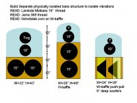
I think these are the most common baffle options. Putting two woofers horizontally near the floor gives the most bass, but a 32" wide cabinet is difficult to make sexy. Vertically stacking two 15" woofers in a 19-24" wide baffle can be sexy...see the Jamo R909 thread and show the glamor picture to your wife...but with naturally less bass than two horizontal near the floor.
I used the Edge simulator to model side-by-side and 2-vertical stacked 15" woofers in this thread. I also used Xlbaffle simulation models in Magnetar's OB thread for the midbass baffle placement.
The AE IB15 speakers are ~ 8" deep, and this pushes a well designed W-baffle width to 20-24". Linkwitz-style W-baffles use a push-pull cone movement that nulls bass mass vibration, but there is a cavity resonance as described in linkwitzlab.com that might need Xover attention. Since the AE15" are pretty deep, the Jamo R909 type vertical stacked baffle is not significantly wider, but I think it is important to physically isolate the bass physical baffle vibrations from the mid-tweet baffle.
Attachments
Thanks for suggestions; I looked them over.
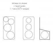
The tweeter I'm using is a 1" alnico CD in almost an 11" diameter waveguide (later maybe a horn). Together with a 12" mid, the only way to get these two drivers plus the 15" woofers on one 24x48 panel (or better for my house, a 20x48), is to put one 15" on a side wing. The Dipole15 driver is closer to 16" effective diameter (and it's not the same driver as the IB15: http://web.archive.org/web/20040307231755/lambdacoustics.com/drivers/DIPOLE15.html ).
I tried to make a scale drawing with the baffle equivalent to 24x48. The oblique packing won't work (and looks strange too). The drivers require close to 44" vertical spread with spacing: 16" + 12.5" + 11". Fortunately, with a 2" margin about woofers on their respective panels, the magnet structures of the 15" woofers should clear, meaning the side wing can work without being overly large.
But anyway, how bad is a 15" woofer on a side wing compared to an all vertical presentation? And what is maximum frequency of x/o for this configuration to avoid problems (200 Hz)?
Thanks, Robert
Attachments
Current Thoughts
I've been a little busy lately, but here is the system configuration that is going to be evaluated:
Supertweeter: RAAL 140-15D
Alternates: Ionovac
Ionovac.com
Roger Russel
HF Crossover: passive 1st-order 5~7 kHz, with slope for supertweeter increasing below 2 kHz.
Mid-High: Great Plains Audio 288-16H Alnico with aluminum diaphragm, tangential surround, and no bugscreen
Alternates: Yamaha JA6681, Vitavox S2, JBL 435Be or 2435 w/Aquaplas treatment
Horn/Waveguide: Azura AH-425
Alternates: custom OS, custom conical with Quadratic Throat transition or similar, Tractrix
Mid Crossover: passive 2nd/3rd order 700~900 Hz (measured acoustic slopes, not electrical). This will take the longest time to design, with extensive MLSSA and ARTA measurements in the time domain, frequency domain, CSD, on and off-axis. One thing that helps is that mid-high and midbass have similar overall diameters, and 2-way professional monitors have used crossovers in this region going back to the Lansing Iconic.
Midbass:
12" - Great Plains Audio 414 Alnico, 18Sound 12NDA520 Neodymium
15" - Lambda TD15M (future Alnico or field-coil version), Great Plains Audio 416 Alnico
Bass-Fill Crossover: active, parametric equalization, 160~320 Hz lowpass, with separate amplification. The bass-fill drivers will be highpassed around 50 Hz to control excursion and hand-off to monopole subwoofers.
Bass-Fill: 18" Beyma SM118NA, Beyma 118Nd/W, JBL 2242, future Lambda 18" driver
The simple open baffle will be tried with no damping on the rear (dipole) as well as a semicylindrical curved felt blanket that wraps around the rear, with a modest amount of recycled cotton filling directly behind the 18" driver (quasi-cardioid). The main purpose of the adjustable parametric equalization is to compensate for the differing efficiency and bass rolloffs of the two different OB setups, as well as proximity effects from nearby room boundaries.
I will not be trying the "alternates" - they are offered as suggestions for people who already have these drivers, not as an eBay buying guide (stay away, stay away!).
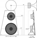
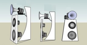
The first drawing shows the 12+18 combination, the second the 15+18 combination. Both share a screw or bolt-in interchangeable side wall and baseplate assembly. (The dimensions are relative to the faceplate of the front baffle.)
I've been a little busy lately, but here is the system configuration that is going to be evaluated:
Supertweeter: RAAL 140-15D
Alternates: Ionovac
Ionovac.com
Roger Russel
HF Crossover: passive 1st-order 5~7 kHz, with slope for supertweeter increasing below 2 kHz.
Mid-High: Great Plains Audio 288-16H Alnico with aluminum diaphragm, tangential surround, and no bugscreen
Alternates: Yamaha JA6681, Vitavox S2, JBL 435Be or 2435 w/Aquaplas treatment
Horn/Waveguide: Azura AH-425
Alternates: custom OS, custom conical with Quadratic Throat transition or similar, Tractrix
Mid Crossover: passive 2nd/3rd order 700~900 Hz (measured acoustic slopes, not electrical). This will take the longest time to design, with extensive MLSSA and ARTA measurements in the time domain, frequency domain, CSD, on and off-axis. One thing that helps is that mid-high and midbass have similar overall diameters, and 2-way professional monitors have used crossovers in this region going back to the Lansing Iconic.
Midbass:
12" - Great Plains Audio 414 Alnico, 18Sound 12NDA520 Neodymium
15" - Lambda TD15M (future Alnico or field-coil version), Great Plains Audio 416 Alnico
Bass-Fill Crossover: active, parametric equalization, 160~320 Hz lowpass, with separate amplification. The bass-fill drivers will be highpassed around 50 Hz to control excursion and hand-off to monopole subwoofers.
Bass-Fill: 18" Beyma SM118NA, Beyma 118Nd/W, JBL 2242, future Lambda 18" driver
The simple open baffle will be tried with no damping on the rear (dipole) as well as a semicylindrical curved felt blanket that wraps around the rear, with a modest amount of recycled cotton filling directly behind the 18" driver (quasi-cardioid). The main purpose of the adjustable parametric equalization is to compensate for the differing efficiency and bass rolloffs of the two different OB setups, as well as proximity effects from nearby room boundaries.
I will not be trying the "alternates" - they are offered as suggestions for people who already have these drivers, not as an eBay buying guide (stay away, stay away!).
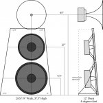
The first drawing shows the 12+18 combination, the second the 15+18 combination. Both share a screw or bolt-in interchangeable side wall and baseplate assembly. (The dimensions are relative to the faceplate of the front baffle.)
Attachments
The 15+18 combination. Both baffles use golden-section ratios (1:1.272:1.618) for the midbass driver. I've had good luck with these ratios for direct-radiators - it made all the difference in the Ariel, where the offset locations sounded and measured better than the centered locations. Standing-waves on the baffle are real and measurable (they show up in the nearfield by "scanning" the microphone across the baffle).
Attachments
Esthetics
Found these pictures over at the Audio Voice Acoustics site. A simple semi-gloss white finish would look nice on the open baffle, and would complement the color of the Azurahorn. I'll be asking my neighbor Thom Mackris over at Galibier Design for Denver-area wood and metal craftsmen that do high-quality work.
Found these pictures over at the Audio Voice Acoustics site. A simple semi-gloss white finish would look nice on the open baffle, and would complement the color of the Azurahorn. I'll be asking my neighbor Thom Mackris over at Galibier Design for Denver-area wood and metal craftsmen that do high-quality work.
Attachments

HF Mounting Frame
Also found this picture over at the Audio Voice Acoustics site, with an excellent idea for a simple metal frame to mount the mid/high horn and ribbon supertweeter. (A C-shaped section in the middle for the mid/high horn and the top of the platform for the supertweeter.)
Also found this picture over at the Audio Voice Acoustics site, with an excellent idea for a simple metal frame to mount the mid/high horn and ribbon supertweeter. (A C-shaped section in the middle for the mid/high horn and the top of the platform for the supertweeter.)
Attachments

Hi Robert,
I put up a post on my forum regarding your project. Didn't want to hijack Lynn's thread any more.
http://www.aespeakers.com/phpbb2/viewtopic.php?f=1&t=1688
Feel free to comment. I think this option would be much superior to any single 18" that is available or could be made available. The 2 Dipole15's displace over 4L of air compared to about 1.5L for even the best of 18's currently available.
John
Hi Robert
have a look at John Kreskovsky's tech paper about the topic of power matching between mid and bass.
http://www.musicanddesign.com/PowerMatching.html
Bottom line - using a (mid-)bass L-shaped OB with one speaker firing to the side may look ugly at a first glance but may also sound superior to anything else.
I my own approach realising a high efficiency / high output / all OB design, my first experiments with that arrangement turned out very promising.
My mid-bass OB right now is (basically) around half a meter by half a meter and a 90 degree wing with half a meter for the second speaker.
Goal is a roughly 120 dB / 1m at extreme low IM up from 100Hz intended and usable also as mid/ far field monitor.
Current ingredients are a PRO AMT in true dipole configuration (which will undergo some additional modifications as soon as time allowes) - two PRO 6,5" (power/ excursion split operated) - two ultra low Rms PRO 15" (also power/ excursion split operated).
-----------
Lynn, good to see your project developing. Congratulations for jumping the 4000.
Regarding structure of OB speakers I realy wonder why "flying" isn't more popular .
Greetings
Michael
mige0 said:
Current ingredients are a PRO AMT in true dipole configuration (which will undergo some additional modifications as soon as time allowes) - two PRO 6,5" (power/ excursion split operated) - two ultra low Rms PRO 15" (also power/ excursion split operated).
Can you say what you are using?
Beyma tweeter
PHL or other mid
and which bass driver?
Thank you,
Chris
Lynn,
Where are you going to place your RAAL?
Any update on AH-425?
Canius,
I think RAAL needs to be placed on the same vertical axis of the AH-425 and not next to it.
Where are you going to place your RAAL?
Any update on AH-425?
Canius,
I think RAAL needs to be placed on the same vertical axis of the AH-425 and not next to it.
agent.5,
Tomorrow I will try to make much precise project with raal on top.
I dont know how many inch must be between edge of horn to center of raal...
Best
Caninus
Tomorrow I will try to make much precise project with raal on top.
I dont know how many inch must be between edge of horn to center of raal...
Best
Caninus
caninus80 said:agent.5,
Tomorrow I will try to make much precise project with raal on top.
I dont know how many inch must be between edge of horn to center of raal...
I don't know either. Maybe someone that have used RAAL can tell us.
Re: HF Mounting Frame
The easiest metal framing is to use 80/20 aluminum extrustions, assuming you want simple shape and not fancy design and curves.
Prices are good at their Ebay store.
http://stores.ebay.com/8020-Inc-Gar..._W0QQcolZ4QQdirZ1QQfsubZ6482273QQftidZ2QQtZkm
with an excellent idea for a simple metal frame to mount the mid/high horn and ribbon supertweeter.
The easiest metal framing is to use 80/20 aluminum extrustions, assuming you want simple shape and not fancy design and curves.
Prices are good at their Ebay store.
http://stores.ebay.com/8020-Inc-Gar..._W0QQcolZ4QQdirZ1QQfsubZ6482273QQftidZ2QQtZkm
- Home
- Loudspeakers
- Multi-Way
- Beyond the Ariel