tbh if you use another scale 50dB to 60dB your data is imo not that good as you believe. There is the same hole around 1k (mayby not that deep as just shown) and really is of concern that the phase is already +180 deg way above the cosmetic cut-off 320Hz and there is a serious resonance just above 400Hz which is also present in the phase curve.Hi,
my own measurements of a similar (IMHO even better, in some ways) radial hypex horn, the Yuichi Arai A-320FL, with the JBL 2450J + Truextent Be diaphragm:
https://www.diyaudio.com/community/threads/jmlc-and-yuichi-horns-measurements.395046/post-7262359
I would HIGHLY recommend this driver+dia (the 2" exit version) to mate with the Yuichi or TAD horns, which were all designed for the TD-4001 driver, which in turn has the exact same internal geometry as the JBL 2450.
Any other driver-horn mix-and-match is a bit of a compromise, and specifically often gives up something in the lowest octave. Also, the 4" Truextent Be dia's are really clean all the way up to 20kHz.
Marco
Yes I looked at his measurements in the other thread and see a 3 - 4dB dip at 1kHz, somewhat obscured by the scale factor used on the graph. I don't see a pronounced phase flip at 1kHz in my measurements. Here it is with phase.
Swept 300Hz - 20kHz, direct amplifier drive, no EQ or processing of any kind, on axis a few CM forward of Yuichi A290 horn mouth. Calibrated UMIK-2 mic, measurements taken 20230210. (In normal use I cross at 840Hz and 10kHz, recommended lowest XO point from Yuichi Arai for this horn is 600Hz)

Fundamental + 2nd and 3rd Harmonic + Noise Floor

Impulse Response

Swept 300Hz - 20kHz, direct amplifier drive, no EQ or processing of any kind, on axis a few CM forward of Yuichi A290 horn mouth. Calibrated UMIK-2 mic, measurements taken 20230210. (In normal use I cross at 840Hz and 10kHz, recommended lowest XO point from Yuichi Arai for this horn is 600Hz)
Fundamental + 2nd and 3rd Harmonic + Noise Floor
Impulse Response
@kevinkr
You have a quite uncomfortable scale for the driver ;-) So every issue a magnified. Nevertheless, imo there is serious issue in your setup you should investigate as the dip around 1k is looking a little "ill" more or less like a "V". sfairc the Radian 2" driver has this rapid opening flare section compared to the 1.4" version, right? This might be an issue. Du you have a fin horn version?
What you could do.
Measure the impedance of the driver free-air and attached to the horn. Does the second driver behave the same?
Show us pictures of the horn entry, the adapter and the driver exit. Do you have a horn clone?
Have you measured the Radian also attached to another horn?
Try a different 2" driver and measure the horn.
Is would be interesting to see the fr from 200Hz on. The loading capability of this horn seem to be not as good as gathered from the advertised 290Hz. No wonder, it is simply too short (380mm without adapter).
I'd be interested to see whether it is equalisable, or to what extent it can be equalised and why.
I agree that the dip is significant, I'd say Kevin has used a similar scale to what I'd use under the circumstances.
I agree that the dip is significant, I'd say Kevin has used a similar scale to what I'd use under the circumstances.
Last edited:
I've had the drivers for about 18 months and may still have measurements on the old JBL2380A horns I originally put them on. I will need to dig. I did impedance measurements at some point, they matched the factory measurements reasonably well on the 2380A horn - I don't have them anymore and will need to do them again. It appears that perhaps it can be effectively equalized out. See below. Prior off axis measurements did not highlight any issues but may not be the whole story. Still investigating and trying to understand what is going on. (And I have a long way to go in my learning.)
The horn is a clone made by Athos, specifically the Yuichi A-290 which has fins. These horns were CNC from solid blocks of baltic birch plywood.


The amplifiers are not designed to operate below 300Hz so measurements below 300Hz may be affected - given the modest power levels performance should be acceptable.
Both horns and drivers exhibit virtually identical performance, what is presented here is representative for both channels. Note that is through the crossover with EQ applied so the range of interest is 800Hz to 10kHz. The previous measurement showing the notch was a direct measurement.
This is my feeble attempt so far at 2 meters from listening position, center of room. Both channels match closely even with the room interfering. Note that Yuichi states very clearly that this horn is not intended to be crossed lower than 600 - 650Hz. Currently crossing at 840Hz. I probably can do better than this. I still have one unused DSP filter slot, but probably need to/could do a better job above 2kHz. Dirac 3 is applied at the system level and makes further corrections to the overall FR.

The system is in daily use so swapping drivers is not something I can immediately do, but I do have a pair of JBL2440 which I can update with 2441 OEM diaphragms and I can do a swap on one channel to do a quick measurement to see what the difference is.
Docali I greatly appreciate your feedback and advice and will try to act on it over time.
The horn is a clone made by Athos, specifically the Yuichi A-290 which has fins. These horns were CNC from solid blocks of baltic birch plywood.
The amplifiers are not designed to operate below 300Hz so measurements below 300Hz may be affected - given the modest power levels performance should be acceptable.
Both horns and drivers exhibit virtually identical performance, what is presented here is representative for both channels. Note that is through the crossover with EQ applied so the range of interest is 800Hz to 10kHz. The previous measurement showing the notch was a direct measurement.
This is my feeble attempt so far at 2 meters from listening position, center of room. Both channels match closely even with the room interfering. Note that Yuichi states very clearly that this horn is not intended to be crossed lower than 600 - 650Hz. Currently crossing at 840Hz. I probably can do better than this. I still have one unused DSP filter slot, but probably need to/could do a better job above 2kHz. Dirac 3 is applied at the system level and makes further corrections to the overall FR.
The system is in daily use so swapping drivers is not something I can immediately do, but I do have a pair of JBL2440 which I can update with 2441 OEM diaphragms and I can do a swap on one channel to do a quick measurement to see what the difference is.
Docali I greatly appreciate your feedback and advice and will try to act on it over time.
Last edited:

From the dumb question department. I am building a BTA using Altec 416 woofers. Gary Dahl built his BTA using 416's in a 3 cu. ft. sealed box, I think moderately, but not lightly, damped.
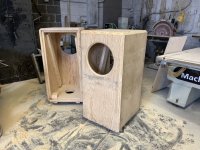
My box is more like 8 to 9 cu. ft. box, I call Cookie Monster since it was momentarily blue. (see image) It was built for Altec 604E's using 2 in. plywood. I had planned to use a 6" pipe as a vent in the bottom and tune the box with different lengths of pipe. My experiments with box tuning were a bit of a failure. I had difficulty correlating what I perceived and measured with simulations or other general concepts of tuning. Not the least of the difficulties were strong room modes.
Gary's design intends to avoid large excursions of the 416 by using the sealed box at 3 cu. ft. When I have simulated drivers in a sealed box I have not noticed significant response or excursion differences across a moderate range. Joseph Crowe also published a sealed alignment design for the SB Audience Bianco 15" woofer and demonstrated that there was not a lot of sensitivity to sealed box volume in the moderate range.
I know the long axis dimension is not ideal for standing waves, but other than that, are there any negatives to using the 9 cu. ft. box sealed with the 416? I will experiment with the open back and heavy damping like reported by Gary Primm. I could easily block off some volume and try that should a 3 cu. ft. volume have better response. Should I try to extend the 416 lower with vents? Or, is it already well established the sealed alignment is only compromised by trying vents. What about Lynn's idea for restrictive vents?
Cheers,
Jamie
Attachments
I would be interested in seeing your measurements of the JBL 2380a horn. Thank you for posting.I've had the drivers for about 18 months and may still have measurements on the old JBL2380A horns I originally put them on. I will need to dig. I did impedance measurements at some point, they matched the factory measurements reasonably well on the 2380A horn - I don't have them anymore and will need to do them again. It can be effectively equalized out. See below.
The horn is a clone made by Athos, specifically the Yuichi A-290 which has fins. These horns were CNC from solid blocks of baltic birch plywood.
View attachment 1143134
View attachment 1143135
View attachment 1143136
The amplifiers are not designed to operate below 300Hz so measurements below 300Hz may be affected - given the modest power levels performance should be acceptable.
Both horns and drivers exhibit virtually identical performance, what is presented here is representative for both channels. Note that is through the crossover with EQ applied so the range of interest is 800Hz to 10kHz. The previous measurement showing the notch was a direct measurement.
This is my feeble attempt so far at 2 meters from listening position, center of room. Both channels match closely even with the room interfering. Note that Yuichi states very clearly that this horn is not intended to be crossed lower than 600 - 650Hz. Currently crossing at 840Hz. I probably can do better than this. I still have one unused DSP filter slot, but probably need to/could do a better job above 2kHz. Dirac 3 is applied at the system level and makes further corrections to the overall FR.
View attachment 1143131
The system is in daily use so swapping drivers is not something I can immediately do, but I do have a pair of JBL2440 which I can update with 2441 OEM diaphragms and I can do a swap on one channel to do a quick measurement to see what the difference is.
Docali I greatly appreciate your feedback and advice and will try to act on it over time.
Gary's design intends to avoid large excursions of the 416 by using the sealed box at 3 cu. ft.
I also thought that was the volume he used, but Lynn, who should know, mentioned a few posts back that it was 3.5 cu/ft. He is now planning to use 3.9, which I believe has more to do with shape/dimensions as with volume, but maybe he can comment. One more thing is that I believe they were generous with stuffing. I find his woofer placement interesting and I am sure he has done this after careful considerations. Also the small plinth/base and the curved edges, although I am not sure what the "real" (i.e. subjective) impact this has.
I am building three closed boxes with lab12's for the bottom octave (not that I need three , but to try to get a more uniform response, using MSO software for a start). I read here Lynn saying a sub is not really needed, but I think it would depend on taste/music type/room size.
Regarding larger boxes, they were the classic solutions, so they should work well.
Unfortunately after extensive searching it appears I deleted those measurements at some point in the past. I don't have anything that I would consider helpful. 🙁I would be interested in seeing your measurements of the JBL 2380a horn. Thank you for posting.
Correct.I agree with everything, except maybe not "including all reverberations." This sounds like putting too much weight into the reverberation field. The ear can filter out the reverberation better and better as the frequency goes up and so depending on the DI the room reverberation gets basically ignored and the direct field becomes the dominate perception attribute. But agreed - the reverberant measurements shouldn't be too far off the direct field ones - just not equal in perception to the direct field.
In hall acoustics 50 ms is quoted (by Barron) as a limit for the reflections to have an effect on tone coloration.
For temporal summation (Sharf, Houtsma, Zwicker) the limit appears to be 125 ms.
Thus the longer reverberations don't need to be included, the impulse response can be limited to 100 ms.
However, for a 100 ms impulse response window there is little data for the value of the downward slope with increasing frequency. The measurements on my system indicate that the slope (and 20 kHz crossing of the linear fit) would be 3/4 of the dB values mentioned previously, ... for what it is worth.
The direct response on the listening axis (average 15°) and the total response (including all reverberations) are more common. E.g. fig. 4 and fig. 7 of https://www.stereophile.com/content/jbl-4367-studio-monitor-loudspeaker-measurements
Swak, I agree I think a larger box is fine. My proposal is that the design is not very sensitive to the volume of a sealed box across a fairly wide range, in this driver approach. I think the key attributes are a driver with low Q, low mass cone and strong magnet to have good HF extension and very good impulse response. I am guessing any box could be tuned to minimize LF cone excursion, but the sealed box is also low Q, which maintains good impulse response through the driver resonant frequency, Fs.
By using a smaller box, Gary can push the F3 higher, I think, and further minimize cone excursion. And, he had planned to use a sub or helper woofer. Tuning the box higher, sealed and damped, he’s keeping the 416 in the sweet spot of very low cone excursion.
With my big box, I could start by filling the box to 3.5, then expand the box. That sequence appears solid. Or, just use the big sealed right off. The next step after that might be to try Gary Primm’s OB approach, then finally vents.
I think that the organizing principle is to progressively allow further LF extension but with deliberate attention to cone excursion and Q. I have heard about an approach for this driver in a TL where it is tuned very low. This results in a very rolled off LF response with Fb below FS such that cone excursion goes to minimum at the bottom of the bow. The LF energy may be well down, but with some room boost and placement it is nice ambient energy.
Just curious what folks have tried with this 416. Since LF is so hard to measure in room, I think it can be interesting to hear about subjective results.
Cheers,
Jamie
Given my previous post about response anomalies in the Yuichi A290 horn driver by a Radian NEO950PB-16 driver I thought I ought to share the results with a JBL "2441" (2440 with 2441 16 ohm OEM diaphragms) My conclusion is that path length between the phase plug and horn entrance is critical in this design.
This is just the horn response with no crossover or EQ, at a distance of ~ 3inches from the horn mouth. Off axis angles are approximate. A simple shelving high pass would likely be all that is needed to EQ it.

This is just the horn response with no crossover or EQ, at a distance of ~ 3inches from the horn mouth. Off axis angles are approximate. A simple shelving high pass would likely be all that is needed to EQ it.
Free air impedance and phase measurement for Radian NEO950PB-16 and JBL "2441" which is 2440 with 2441 16 ohm OEM diaphragms.
Radian NEO950PB-16 in free air

JBL 2441 16 ohm in free air

Radian NEO950PB-16 in free air
JBL 2441 16 ohm in free air
What attracted me to the jbl 2451 was three main things:
- It is "snout-less", exit is right at the end of the phase plug.
- The phase plug is aiming at delivering a plane wavefront exit
- It is the cheapest one to buy used due to its odd bolt pattern.
I think that if all drivers, regardless of technology used, would be designed to conform the first two above it would make horn design much easier for everyone. All we would have to think about were to pick the right exit size.
//Anders
Nice. Very good response. The horn seems to work well. What kind of smoothing is applied? I would expect more resonances beyond 10k fron a non-Be diaphragm.Given my previous post about response anomalies in the Yuichi A290 horn driver by a Radian NEO950PB-16 driver I thought I ought to share the results with a JBL "2441" (2440 with 2441 16 ohm OEM diaphragms) My conclusion is that path length between the phase plug and horn entrance is critical in this design.
This is just the horn response with no crossover or EQ, at a distance of ~ 3inches from the horn mouth. Off axis angles are approximate. A simple shelving high pass would likely be all that is needed to EQ it.
View attachment 1144135
The 2441 seems to be a quite long driver. Does it have a longer exit section?
This would indicate that the Radian drivers either have an unknown issue or are not suitable with the very short adapter. If you could show us a picture of the Radian without horn pointing upwards then we could assess the shape of it's exit section.
Free air impedance and phase measurement for Radian NEO950PB-16 and JBL "2441" which is 2440 with 2441 16 ohm OEM diaphragms.
Radian NEO950PB-16 in free air
View attachment 1144137
JBL 2441 16 ohm in free air
View attachment 1144138
Each driver's impedance should also be measured attached to the horn. The difference to free-air would tell us how good the driver is "damped" attached to the horn.
The JBL 2441 seems to be a very nice performer. A minimum impedance never falls below about 12 Ohms and all minimums between the peaks have nearly the same level. It seems to be out of production since some time?
Hi Docali,
This is the impedance and phase plot for the right channel horn and driver, driver on horn, driver free air. I am going to swap the 2441 later today, I will take impedance and phase plots for both.


The JBL 2440/2441 has been out of production for decades. My very vague and possibly incorrect recollection is that alnico was in short supply sometime in the late 1980s. early 1990s and all of these drivers were discontinued and replaced with ferrite based versions.
This is the impedance and phase plot for the right channel horn and driver, driver on horn, driver free air. I am going to swap the 2441 later today, I will take impedance and phase plots for both.
The JBL 2440/2441 has been out of production for decades. My very vague and possibly incorrect recollection is that alnico was in short supply sometime in the late 1980s. early 1990s and all of these drivers were discontinued and replaced with ferrite based versions.
Last edited:
Very strange. The following peak from free-air is almost still existing attached to the horn:

Do you have a voltage amplifier? Do you use a protection capacitor for the measurement?
But looking at the impedance attached to the horn your amp (voltage) at just below has a load of more than 40 Ohms. You could easily calculate the power that is resulting maybe for 1V signal und just 500Hz above you have a load of about 15 Ohms and together with the same 1V signal produces more power because the amp is pushing more current into the smaller load. This could explain the rising response from 970Hz to 1k5.
For the JBL driver I expect a much more even impedance plot attached to the horn.
I can show the example of the 18sound ND3N driver free-air and attached to the TH4001:

The adapter used was not really optimal but you can see the effect that the combined impedance is quite constant in the LF region. I would expect a similar difference for the JBL driver.
The adapter used was not really optimal but you can see the effect that the combined impedance is quite constant in the LF region. I would expect a similar difference for the JBL driver.
Directly driven by SE DHT power amplifierr, source impedance is ~ 1.5 ohms, no capacitor, so not quite a perfect voltage source. I actually measured the voltage drive across the driver over the entire operating range and saw considerably less than a 1dB variation in output voltage over the entire range from 300Hz - 20kHz. It is very puzzling indeed.
The JBL drivers are now installed and I used one of the captures to generate a new filter for my DSP based parametric EQ. Interestingly REW actually suggested a -2.3dB dip at 1.34kHz with a Q of 1.16. I thought a shelving filter was in order, but what do I know. (Actually not much, and lot to learn.)
The JBL 2440/2441 driver throat distance phase plug to mouth is almost twice the distance compared to the Radian.
I will do an impedance measurement this afternoon and post it here. Again many thanks for your considerable assistance and encouragement. 😀
Last edited:
- Home
- Loudspeakers
- Multi-Way
- Beyond the Ariel