Same thing with my other set of leads, with the tips clamped together and otherwise undisturbed. I am accustomed to the issue of contact pressure variation and wasn't allowing that as a variable.
Gary Dahl
Gary Dahl
The Tonghui mentioned before has a 5-terminal measurement configuration which solves the problem of measurement for equivalent series resistance.
I would look for it or something similar.
I would look for it or something similar.
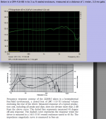
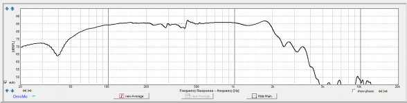
Gary,Below is a GPA 416-8B in its 3 cu ft sealed enclosure, measured at a distance of 1 meter, 3.0 ms gate.
Interesting that the 6 (or 7) dB upper peak in the 15" GPA 416-8B is almost an octave higher than the 12" GPA 414-8B.
The frequency response variation between the 416 and the JBL 2226 are rather large in the octaves above the crossover point, around 15 dB at 2500 Hz.
Without a radically different crossover for each, the two speakers certainly would sound quite different, I wonder if Lynn used different crossovers for each when he found his preference for the GPA.
Art
Attachments
In one word. FLUKEYes, of course. But I just can't get stable, repeatable readings. I need a better meter. Any recommendations?
I have a 867b now, but have owned 8060, 77, 87, 88, 89. Also have done service and NIST cal for all these (and most other brands) so this is coming form a bit of experience. Unless you hurt them they work and give reliable consistent results and top notch accuracy. An older 87 is quite nice for the money. The newer 289's look nice. Ebay my man 🙂
The one feature the 867b has that no other meter has is component test. With experience this can seriously speed trouble shooting blown ckts. Friend built one for scope use that would supply enough current to test >2KA triac's/thyristors (hockey pucks). It would annihilate lesser devices with a blinding brite flash, mushroom cloud and a hole in the roof
That's when you know it's time to take a break and have a beer 🙂
You can do good DCR measurements with the Woofer Tester II, or the WT3. They will show the impedance curve and also tell you the DCR. You can check this against a known resistor. More repeatable than most ohm meters.
You can do good DCR measurements with the Woofer Tester II, or the WT3. They will show the impedance curve and also tell you the DCR. You can check this against a known resistor. More repeatable than most ohm meters.
Goran (gornir) did a nice little comparison on the two testers here:
www.audioexcite.com 2013 October
..and the newer DATS is likely similar to the older WT3, though with more features.
regarding Rdc measurement - 100mA CCS and DVM of any class will give precise enough measurement ;
regarding plain Ohmic reading-if measurement of high sens driver is in case , where breath of fly can influence reading , shunt resistor across VC can be useful
then all one need to know is readout with probes closed (0R2 to 0R3 in most cases) and where is that damn calculator
regarding plain Ohmic reading-if measurement of high sens driver is in case , where breath of fly can influence reading , shunt resistor across VC can be useful
then all one need to know is readout with probes closed (0R2 to 0R3 in most cases) and where is that damn calculator
Gary, if you do a close mic pressure measurement of the 416b, could you please post the raw impulse as a txt float list or wav format file?

maybe need kelvin clips
Kelvin (4-wire) resistance measurement : Dc Metering Circuits
Same thing with my other set of leads, with the tips clamped together and otherwise undisturbed. I am accustomed to the issue of contact pressure variation and wasn't allowing that as a variable.
Gary Dahl
Kelvin (4-wire) resistance measurement : Dc Metering Circuits
Nice catch

Similar techniques in process calibration. 4 wire twisted pair also reduces common mode noise from the measurement.
Hoping to get to it tomorrow. According to the protocol on mh-audio, the upper frequency limit of the measurement will be only 216 Hz, accounting for the baffle size. Also, it seems that aligning the mic with the driver's center is problematic because of the vented dust cap. Will placing the microphone away from the center reduce the measurement accuracy yet further?
Gary Dahl
Gary Dahl
Hoping to get to it tomorrow. According to the protocol on mh-audio, the upper frequency limit of the measurement will be only 216 Hz, accounting for the baffle size. Also, it seems that aligning the mic with the driver's center is problematic because of the vented dust cap. Will placing the microphone away from the center reduce the measurement accuracy yet further?
Gary Dahl
Hi Gary
Keep in mind the very near field measurement (which I believe Don Keele described in an old AES loudspeaker anthology) is better than nothing but is has several issues which make it much less often used in engineering now days.
If one were trying to figure out a crossover for example, one would want a data set taken at a distance where the response has stopped changing in shape as a function of distance (reflecting what you hear at a normal listening distance).
If one wanted a measurement that allowed one to scale the SPL to a different distance, then to get reliable data, one needs to follow the criteria here;
Far-field Criteria for Loudspeaker Balloon Data Synergetic Audio Concepts
Thankfully for home sized woofers it is easy, you can ignore that stuff or like we do at work with large subwoofers, measure at 10 meters (-20dB re 1 Meter) and then drive with 28.2V (+20dB over 2.82V) to get a 1 meter 2.8 V curve..
This can only be done outdoors and where any building is ideally many many times the mic to speaker distance.
When weather and circumstances permit, the out doors is an ideal place to measure what the loudspeaker itself is doing.
If you have a step ladder or other easy way to get it in the air (I do this so often for work that I made a tower), then your only reflection (the ground) is reduced in intensity by the inverse square law (difference between the shorter and longer path) and so even without gating, one can get “the speaker by itself” which is the only part you can possibly address or want to try to address.
Best
Tom Danley
Hi Gary
Keep in mind the very near field measurement (which I believe Don Keele described in an old AES loudspeaker anthology) is better than nothing but is has several issues which make it much less often used in engineering now days.
If one were trying to figure out a crossover for example, one would want a data set taken at a distance where the response has stopped changing in shape as a function of distance (reflecting what you hear at a normal listening distance).
Best
Tom Danley
In many cases near field is all you can do. But one should never use near field data any higher in frequency than absolutely necessary. I can't believe that some people measure horns near field. Wow - is that ever wrong.
I think they measure those horns (like Azura horn) real close to make them look much better then they are and sell them to people that don't know better. All the midrange and treble horns I have ever measured (in or outdoors) measure much different at a few feet then at the mouth. Typically an octave or two higher (or more) in the low end drop off. I've even seen where bass horn sellers measure the bass horn inside the horn. 🙂 Normally you need to be at least 6-10 feet back to see what's going on with any of them, and that's on axis.
Last edited:
POH,
When developing a raw frame driver it can be helpful and informing to measure very close to individual components to see what each part is contributing and this is one case where that type of analysis can be useful.
On the other hand measuring any waveguide inside the lens seems very suspicious and would surely hide or discount the real radiation pattern of the horn past the termination point. I have never looked at any polar plots of any waveguide at less than 1 meter and at greater distances. I suppose if you are looking at distortion contributions from the throat of the horn you could measure internally, but that would not be something you would normally see published as a specification that I know of. I imagine that Earl has done this while working on his theory about homs, he can answer that question.
What i'm talking about is people that are just getting their feet wet with horns in the hifi world where they take a look at the manufactures "response curves" measured at or in the mouth of the horn then purchase the horn based on the pretty graph for their project. It's like selling a car that gets 45 MPG - but only down a 20 degree or more hill. How hard is it to take the horn outside and measure it at 2 meters?
Last edited:
- Home
- Loudspeakers
- Multi-Way
- Beyond the Ariel