his true bass is still provided by 4 or 5 stacked 10" bass drivers in individual sealed cabinets per channel, no ports.
hmm, there are better ways to skin a cat? The ceiling bass horns he built was a feline tragedy?
 We never know when to quit
Apparently not a tragedy. Instead a useful and needed link between the round horn he had used, in a much smaller space, an apartment in Boston, and the rather huge space he has as a listening room now, well outside of Boston. He kept the round horns.
I presumed tragedy based on what you said. It appears he attempted to replace the sealed cabinets with bass horns and failed - I didn't realize he made an intentional effort to complicate the bass in his system using both bass systems. Round horns do the same thing, they force you to do other otherwise wasteful things that could be eliminated with a better thought out profile. Like spreading them out vertically many feet and trying yo get them to integrate in nearfield. So to fix it stick a direct radiator box in there to "inject" some coherence? Cool
Just in case you haven"t stumbled on Romy's site, and the mods will allow me to point you to it.
GoodSoundClub - Romy the Cat's Audio Site
He is Russian born and writes algorithms for a living. He enjoys massacring the english tongue. Look for the Macondo System topic to find out what this maniac actually does.
GoodSoundClub - Romy the Cat's Audio Site
He is Russian born and writes algorithms for a living. He enjoys massacring the english tongue. Look for the Macondo System topic to find out what this maniac actually does.
hi
is anybody aware of a mid bass horn that would work well with the ah425 radian playing up to 700hz ?
and off course as low as possible to make integration with a sub easier .
This conical horn might fill the bill. Pretty easy to build. 🙂
Here is one High Efficiency Speaker Asylum: Tractrix vs. hypex vs. conical - corrected (long with pictures) by Volvotreter the Electro Voice EVM15L is one of the best bass horn drivers ever.
I have attached the elevation dwgs of my 50Hz 1/4 WL mid / bass horn. It is an all ply version as close as possible to my original design with the rear fibreglass section. The 1st 1/2m is conical. Happy to email anyone the cutting dims dwgs if they send me a pm. If anyone can help me do a 3D dwg of this it would be great - particularly to check the edge angles (my brain struggles with intersecting planes) . A pair have been built in Perth - but I have not yet been to check them out yet. Simple to build, but accurate cutting of the edge angles is the secret.
I designed it with HornResp using T=0.6 and a 48Hz Fc from an 8" throat, (later cut down to 11.5" throat dia). The mouth proportion approximates the Golden Mean. My objective was to make the least compromised horn that was comfortable in my room set up. And panels that fit std ply sheet size.
I guess most here will understand the limitations - do not expect it to go flat to 50Hz. Use HornResp to model your driver.
Lynn's thread and not sure it belongs here, but seems to be a broad church. Hoping Lynn will build himself a pair 🙂
An externally hosted image should be here but it was not working when we last tested it.
An externally hosted image should be here but it was not working when we last tested it.
That was an interesting "Tom and Earl" post.This conical horn might fill the bill. Pretty easy to build. 🙂
Here is one High Efficiency Speaker Asylum: Tractrix vs. hypex vs. conical - corrected (long with pictures) by Volvotreter the Electro Voice EVM15L is one of the best bass horn drivers ever.
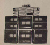
Having extensively used the EV 15L, found the EV 15B to be much better for horn loading, the curvilinear cone of the 15L has much more breakup than the EV 15B.
The 15B had quite a bit more low bass in the same horns pictured below, which were crossed at 200 Hz to the mids which used EV 12L.
Although those horns sounded great, I never felt the need to use bass horns for home use, four bass reflex 15", two tens and a pair of 1" exit HF drivers was as large a system I ever wanted.
30-40 years later a fraction of that cone area suffices for my dynamic requirements...
Attachments
I like them both L & B, the L to me has a bit better tone in the middle mids and at the top end of the bass horn range. In most horns they go about 100 cycles higher then the B, the B is really a great horn driver too.
What's nice about building your own systems is you don't have to pay somebody else to make the mistakes 🙂
What's nice about building your own systems is you don't have to pay somebody else to make the mistakes 🙂
This is also something I have been wondering about, namely: how can people using non-negligible output impedance amplifiers (such as DHTs and to a lesser extent virtually all tube amps) know the extent to which the differences they are hearing between loudspeakers X and Y are due to the 'speakers themselves and not to the different amounts of damping by the amp's output impedance?
( A simple web page illustrating the phenomenon: Loudspeaker Enclosure )
Marco
Mmmmh... nobody cares to comment on this?
Marco
A bass / mid horn like I posted models really flat for electrical impedance in the pass band with a suitable driver - provided there is no back chamber. I have always preferred the sound this way. Not sure about compression drivers - I believe they are flat impedance if the acoustic loading is constant - as the JMLC expansion strives to achieve. No doubt someone will correct me. Horses for courses.
Good point, Marco.
I found it is absolutely mandatory to EQ the voltage at the speaker (or driver) terminals to the same target in every minute detail for valid comparisons. A good baseline target is the voltage response when resistively loaded. This will result in ideally a true bandpass response, completely flat in the passband. If not, you gotta EQ this as well, for these tests to be comparable to other similar tests and reproducible in general. This way you can exchange speakers X and Y on a given amp as well swapping amp X with Y on a given speaker and listen to the effects other than changed frequency response because otherwise this could easily dominate the perceived changes. The corrective EQ is a breeze with any of the popular DSP "room correction tools", for example, but a decent parametric analog EQ will suffice, too (but may be considered less transparent, also very costly).
EDIT: The end user will typically not EQ, so to find out what you may prefer in a given real world situation you'd need to judge the overall effect as is, with response changes and all.
Last edited:
Great content, thanks Lynn.Let's take a look at what stiction really is: granular, nonlinear movement. Push a rock across a concrete pavement, and it will not move smoothly. It'll jump from high point to high point, not smoothly at all.
What happens when we move a spider made of impregnated fabric? It's only smooth when you slowly average the motion over time. In reality, the fibers grind against each other with a slip-strike motion. Try listening to a loudspeaker as a microphone. Is it linear? No. The spider, and to some extent the surround, are optimized for large motions (for long excursions), but no real attention is paid to small motions.
[snip]
Adding linear resistance to a mechanical system is kind of tricky; many of the resistors are prone to stick-slip effects (unlike electrical resistors) and exhibit low-level nonlinearity. Look at all the trouble turntable vendors go to avoid stick-slip in the main bearing, or similar problems with bearing chatter in tonearms.
[snip]
Direct-radiators are constant-acceleration devices. This means at higher frequencies, cone motion is very small, and low-level problems in spider and surround will appear as noise in the 2nd and 3rd harmonic distortion trace. Since it has low correlation with the input signal, it is not cyclic, and will tend to be rejected by the distortion analyzer, especially if the sweep speed is slow (averaging over many cycles).
I've worked in test instrumentation. It's a truism in the business that the instruments do not see what they not designed to look for. When you use a swept spectrum analyzer, you have to be aware the instrument is not designed to see single events, and will give very distorted-looking traces. FFT measurements have their own set of limitations; averaging is useful for extending the S/N ratio of the display, but it rejects non-correlated data as noise. That "noise" may not be noise; it can be granular, non-linear motion, with partial correlation to the input signal. If the test measurement rejects the low-level nonlinearity, that does not mean it is not there.
Rather than treat the loudspeaker as an idealized black box, we have to look at how each element actually performs, and see whether existing measurements capture the behavior or not.
Thinking about how to measure that only partially correlated stiction noise, since it still is partially correlated, time domain sample synchronous averaging whould hit an early brickwall in the noise floor compared the -3dB per doubling of averages that would apply for ideal averaging with truly random noise. With a transducer in current driven mode, small signal sine exitation, the stick-slip actions should partially show up in the induced microphonic voltage so that might be probed for instead of acoustic measurements, additionally one could probe transducer current in standard voltage drive mode as well. The acoustic output would be probably different because with current drive there is zero corrective feedback in the driver at any frequency... which could be a good thing or a bad thing...
Hello Lynn
Isn't that taken care of during the break in process?
Rob🙂
Let's take a look at what stiction really is: granular, nonlinear movement. Push a rock across a concrete pavement, and it will not move smoothly. It'll jump from high point to high point, not smoothly at all.
Isn't that taken care of during the break in process?
Rob🙂
Marco,Originally Posted by marco_gea View Post
This is also something I have been wondering about, namely: how can people using non-negligible output impedance amplifiers (such as DHTs and to a lesser extent virtually all tube amps) know the extent to which the differences they are hearing between loudspeakers X and Y are due to the 'speakers themselves and not to the different amounts of damping by the amp's output impedance?
( A simple web page illustrating the phenomenon: Loudspeaker Enclosure )
Marco
The web page you reference the premise is one speaker with different amplifiers will have different frequency response's.
Lynn case is different. He is comparing 2 different drivers with HIS amplifier.
This comparison is perfectly valid, as long as you have or are willing to build the amplifier used in the testing. And as long as you are comfortable with the subjective assessments. YMMV.
Basically Apples and Oranges.
On a related note, subjective evaluations of JBL drivers that I have seen from various sources tend to state that the JBL 2225 sounds better than the JBL 2226, and the JBL 2220 may be much closer to the Altec than the JBL 2226.
It seems that designing a driver for high excursion and power handling may have its compromises.
Great content, thanks Lynn.
Thinking about how to measure that only partially correlated stiction noise, since it still is partially correlated, time domain sample synchronous averaging whould hit an early brickwall in the noise floor compared the -3dB per doubling of averages that would apply for ideal averaging with truly random noise. With a transducer in current driven mode, small signal sine exitation, the stick-slip actions should partially show up in the induced microphonic voltage so that might be probed for instead of acoustic measurements, additionally one could probe transducer current in standard voltage drive mode as well. The acoustic output would be probably different because with current drive there is zero corrective feedback in the driver at any frequency... which could be a good thing or a bad thing...
Noise in traces of harmonic distortion response?
Input is test signal + noise; output = scaled input + distortion + noise.
Non correlated signal is noise. Some signal that looks like noise is result of system under test producing signals outside bandwidth of measurement system.
In this age, use of longer FFT and longer sample period produces much better result than averaging multiple measurements. Real noise does average out.
Slowest sweep rate is no sweep at all.
Matching sweep of tuned notch to sweep of test signal is old school indeed.
Cross motion of fibers in woven spider? Seems quite remote. But case would very closely follow behavior of bowed string on musical instrument. In static moments string and bow are in fixed contact. Bow drives displacement of string, storing energy. When lateral forces exceed product of normal force with static coefficient of friction of bow on string, string is set into motion by release of stored energy, and if contacting bow energy tapped by kinetic frictional forces.
In view of bow and string analogy, masses for lengths of spider fibers between contact points, and spring constants of those fiber elements as they must be in relationship to bulk spring constant of entire spider, suggest impulses from these stick-slip events would have bandwidth way far away from driver and its coupled air mass.
Got data? Ever listen closely to spider material being flexed in non permanently deforming manner? Spider makes much more noise like highly perforated cone. Radiated signal and sounds of air turbulence.
Could perhaps study back EMF with driver in vacuum chamber with variety of spiders that have been mechanically stressed to induce fiber motion within weave.
Certainly not more than a passing mind adventure for me.
Great content, thanks Lynn.
Thinking about how to measure that only partially correlated stiction noise, since it still is partially correlated, time domain sample synchronous averaging whould hit an early brickwall in the noise floor compared the -3dB per doubling of averages that would apply for ideal averaging with truly random noise.
Stiction comes about because there can be a difference in motional resistance and the static friction. This difference can be great and it can be negligible or it can even be that the motional friction is greater than the static friction meaning that the device wants to be moved. In all cases it is nonlinear and as a result is partially correlated with the signal in that the odd harmonics are correlated while the even harmonics are not. So the correlation will depend on the nature of the stiction, and can be anything from not correlated to almost completely correlated. It will not be noise.
The nonlinear effects of stiction will require that the harmonic content, as a percent, i.e. THD, will rise as the signal level falls. Thus it would be very easy to test for this by simply plotting THD versus signal level (must not be THD + noise!) as the signal level is dropped.
I have never seen any data that would indicate this to be a significant effect, but I will agree if I see some data that shows that it is significant. Data is king, hypothesis is easy.
Last edited:
Thanks Earl, that is great content.
Same idea as switching distortion in class AB amplifiers when devices aren't biased into conduction in linear region of conduction.
Blows spider performance out of the cobwebs.
Same idea as switching distortion in class AB amplifiers when devices aren't biased into conduction in linear region of conduction.
Blows spider performance out of the cobwebs.
.... or it can even be that the motional friction is greater than the static friction meaning that the device wants to be moved.
????? Implies that it takes more force to keep the body moving that it does to start it moving. I.E. as soon as there was any micro movement the force would have to jump instantaneously or the motion would stop.
Last edited:
Viscous frictional behavior?
Basic static friction v kinetic friction: once block starts sliding down ramp, is slides to the bottom. Acceleration is brought into equilibrium with heat dissipation, and sound radiation within block, ramp, and air or liquid medium when present.
Basic static friction v kinetic friction: once block starts sliding down ramp, is slides to the bottom. Acceleration is brought into equilibrium with heat dissipation, and sound radiation within block, ramp, and air or liquid medium when present.
- Home
- Loudspeakers
- Multi-Way
- Beyond the Ariel