with music it is normal, that a higher frequency is "surfing" on a lower frequency with lower amplitude, or technically spoken, in the time domain the derivation of the curve
(x axis is time) can be high, despite the low amplitude of the higher frequency content
(current through a cap I=C * du/dt).
Interesting graph, do you mind sending the equations behind ?
(x axis is time) can be high, despite the low amplitude of the higher frequency content
(current through a cap I=C * du/dt).
Interesting graph, do you mind sending the equations behind ?
One idea is to make an amplifier that goes to say 200V and then the transformer is more easy to make.
Ben, to keep a long story short :
main problem with transformers regarding distortion is, that the main inductivity is strongly dependent on signal level. This is going like this : starting from a low value (say 100mH for a bass transformer, this you measure with a L meter) inductivity wil rise with rising voltage at the primary winding up to the point when core is starting to saturate (say 1.5H). This gives the current a distored part. If the source (amplifier) and the primary winding had zero Ohms DC resistance this distored current would not (!!!) show up in distored voltage, but all the linear impedances in series to the transformer (cables, dc resistance of primary winding, amp output resistance, crossover network (!)) create a nonlinear voltage drop, which will give a distored input voltage at the inner transformer inductivity (measuring at primary winding with a thd meter will not measure distored voltage drop of its dc resistance).
so keep main inductivity as high as possible from the start (lowers the distored current amplitude) and/or keep serial elements small lowers distortion.
Hope this was helpful...
Joachim, if only this would be true..number of secondary winding stays the same (also its complicate layer capacitance), winding volume is restricted, stray inductivity will rise with a square law with raised primary winding number..
Sure, we talked about that and it was not even my idea. You are the expert on electrostatics anyway.
When will i see a transistor amp that can drive direct ?
When will i see a transistor amp that can drive direct ?
I think the key idea between the "direct drive" and the transformer may be impedance related. The transformer will have a single output Z, and an output that is more or less going to maximize the power into that optimal load Z - all other Z being *less* power.
Although I suppose this is not strictly accurate since the matching via xfmr tends to look like a bandpass filter of some relatively low Q...
The tube or other direct drive see it somewhat differently, since it is nominally a very high Z source (especially in the case of high voltage transmitting tubes - which includes 813, 811, 211, 845 and 4-125, etc) and so becomes more "unloaded" as the Z increases, but is still a good match at higher freqs where the nominal Z becomes lower but not very low at all...
Peter Walker showed how changing the matching of the drive transformer gave either wider bandwidth and lower sensitivity or narrow bandwidth and higher sensitivity. Jim Strickland capitalized upon this by using two transformers each matched differently to spread the range that was matched "ideally" creating a virtual transformer that could not be done with a single transformer. It's an imperfect solution since the outputs of the two transformer paths take slightly different amounts of time.
I tested this at one time by comparing the outputs by disconnecting the panels and looking at a pulse on a scope...
let us go back to topic of the thread, Bolsert, one conclusion of your graph :
if it is possible to linearize this nonlinear behavior for higher excusions by some sort of feedback, a considerably lower stator voltage compared to constant charge ELS would be sufficient for higher excursions (current is certainly higher)...couldn´t this be the reason why Mr. Beveridge chose it..?
if it is possible to linearize this nonlinear behavior for higher excusions by some sort of feedback, a considerably lower stator voltage compared to constant charge ELS would be sufficient for higher excursions (current is certainly higher)...couldn´t this be the reason why Mr. Beveridge chose it..?
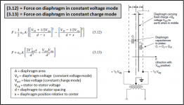
Harold Beveridge from one of his later patents :
<..thus, if one is not interested in frequencies below about 100Hz, the constant charge design and the simple constant voltage design are both suitable.>
Regarding motional feedback in a former patent:
<.. a further feedback system employs a carrier wave applied to the diaphragm of the transducer. The resulting signal on the electrodes is differentiated and negatively fed back to damp speaker response at low frequency resonance.>
Looks like in his later models, he dropped the feedback altogether and used constant voltage drive within small excursions because used above 100Hz...looks like the feedback was not used to lower distortion at higher frequencies..
But this of course does not mean it can not be done...
Interesting graph, do you mind sending the equations behind ?
The graph was created using the standard force equations for constant voltage and constant charge ESLs first published in the Hunt's "Electroacoustics". Personally I find the Baxanadall derivation and description in Section 3.2.2 of the reference below much easier to follow.
Attached is an excerpt showing the equations and relevant figure.
Force was calculated for a range of diaphragm positions(x) with VD = Vpol, and Vsig = 0.
Reference:
P. J. Baxandall, “Electrostatic Loudspeakers,” in
Loudspeaker and Headphone Handbook, J. Borwick, Ed.
(Reed Educational and Professional Pub., Woburn, MA,
1998), pp. 106–195.
Attachments
I've been a big fan of direct-drive ESL amps. My impression is that some transformers in some settings are excellent (like inter-stage coupling). But here is a theoretical question I have:
is there any reason why you couldn't make a transformer play say, 500-2000 Hz absolutely identical to the way a direct-drive amp played it? Would a transformer (esp. a "real world" transformer) always have some shortcoming arising from the nature of being a transformer device?
Ben
This is a concept that I have been tossing around for a while now.
I have done a few spice simulations that shows that this could work.
Use a transformer for >300hz and a low current DD amp for everything below 300hz.
jer 🙂
thank you for the attachement, bolserst..
one comment to my post 21 :
If a low frequency tone brings the foil near to one stator with constant voltage drive, this current will not be relevant (just as you mentioned), but if at the same time there is high upper frequency level (some kHz, violines e.g.) these high upper frequencies are given to an suddenly elevated foil - stator capacity and a nasty (upper frequency) current peak will be the consequence..poor amplifier..
with normal impedance measurement this will not show up...

oops, sorry, but the Baxandall text appears to be out of print..
Ben, I am big fan of Dayton Wright (owning two pairs..)..the high voltage bias resistors failed with mine, sensitivity dropped a lot..I replaced them with 68Mohm 1W HV types from vishay..have fun, Philipp
Ben, I am big fan of Dayton Wright (owning two pairs..)..the high voltage bias resistors failed with mine, sensitivity dropped a lot..I replaced them with 68Mohm 1W HV types from vishay..have fun, Philipp
sorry, my fault, I looked at amazon under <P. J. Baxandall, "Electrostatic Loudspeakers"> and it did not show up..
In my Acoustat 121 bias interfaces.....
I have the bias feed res. setup were i can go from 500meg to 30meg to 10meg.... 10meg sounds the best.... an it like 3-4db more output even if it not...... sound is fast..sweet highs.... best topend i ever had after 30 years of owening Acoustats..all parts in the 121 interfaces stay cool.... amps never strain....
30meg bass gets biger...tone sounds good but top rolls down some....still sounds good.....
500meg stock Acoustat res...... tone gets sweet an BIG!.... but top rolls way down...bass gets fat, soft, spongy like.... parts in the interfaces get hoter.....all this is were the humity is 60% or higher....
If the humity is at 50% are lower....the tone of the 500meg is great...but you can here the amps runout of gas...hehe....it sounds like the bias cant keep up with feeding the panels....
So on paper i get why the bias feed res. being higher would be the best.....
but from a sound standpoint....lower sounds way better...
i have done this with 4pr of ML esl .....there bias feeder res. are 4ea 15meg in se. to give 60meg thought chep 1/4watt res.to the panels......sound can be made much better by droping to about 20meg are lower...with better res......
No res cost less than the 1/4watt 10% carbons sold at ratshak.... like ones used by ML....
I think thay could have done a litte better......
just saying
thanks for all this great info on ESLs............
a must read from Harold Beveridge´s son :
http://www.diyaudio.com/forums/planars-exotics/51103-harold-beveridge-esls-2.html#post719626
..well this will need to be commented on..
http://www.diyaudio.com/forums/planars-exotics/51103-harold-beveridge-esls-2.html#post719626
..well this will need to be commented on..
Thanks for the post info...from Beveridge
At one time i thought that if i put more bias on the panels... i can set my Acoustat bias from 4-7k like the soundlab backplate bias setup...
that this would help 500meg keep up ....an it did.....but i fine that with the 30-10meg works better at the lower bias v.. i gess i can just hear the bias ezer......to high sound get tight...to low run out of gas ....parts amps get hoter....lose output...
Dose any one know what the bias feed res.is in soundlab???are if thay even use one??
I have buds that have Soundlabs......M1...thay cant get the sound & output i am geting with my acoustat......thay wount me to fixs there M1....hehe
there got about $100k....in there setups....thay leave myplace crying...it tuff..
Last edited:
- Status
- Not open for further replies.
- Home
- Loudspeakers
- Planars & Exotics
- Beveridge vs Final ESL Configuration