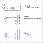
While digging up some circuit diagrams for the Graphene thread, I stumbled on some comparisons I had made between the Final “inverted” configuration and the Beveridge configuration. Figure 1 shows the Final circuit as depicted in their patent(cough cough) and white paper. The circuit elements can be rearranged as shown in Figure 2. Now, the Beveridge configuration is shown in Figure 3. Note that the only difference is where the ground reference is placed.
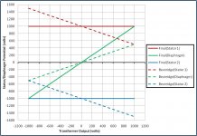
The difference in ground reference would have minimal impact in transformer driven ESLs. But, if you were wanting to drive the ESLs directly with HV amplifiers, the Beveridge configuration has an advantage. The second attachment shows comparison of the stator and diaphragm voltages. Note that the Beveridge configuration swings the diaphragm voltage only half as far as the Final configuration. But, it also swings the stator voltages the same amount in the opposite direction. The difference in voltage potential between the diaphragm and stators is the same, so the resulting force on the diaphragm is the same.
It doesn’t take much thought to realize that this would allow you to replace a single amplifier with two amplifiers of half the voltage output capability. Anybody who ever attempted to design a HV amplifier will know that halving the output voltage requirements is a big deal.
Of course you are stuck with operating in the constant voltage mode.
Beveridge got around this drawback in his direct drive designs by using an ingenious motional feedback system. The average diaphragm position/motion was determined by injecting a low level RF signal and measuring the ratio of the RF signal sensed across the two air-gaps. With this system he was able to reduce distortion from constant voltage mode operation as well as damp the diaphragm fundamental resonance.
Attachments
Last edited:
Hi,
I´m not sure if the Beveridge Feedback were able to reduce THD or if it only reduced and controlled the exaggerated excursion at the ground resonance of the panel as the amp had a low-impedance voltage output in first place.
Controlling current flow on the other hand means controlling charge.
And charge is whats defines the position of the membrane in a CV-ESL.
So I´d rather expect to see a current output amplifier. ;-)
jauu
Calvin
I´m not sure if the Beveridge Feedback were able to reduce THD or if it only reduced and controlled the exaggerated excursion at the ground resonance of the panel
As with any motional feedback system, the control loop doesn't know the difference between distortion and response deviations.
The feedback system attemps to drive the difference between input and output to zero no matter what the source.
Distortion harmonics and response deviations are both reduced by the same ratio.
That being said, I should clarify that the Beveridge feedback loop only had significant gain below 100Hz.
But this is where diaphragm excursion starts to get significant anyways, and the square-law distortion from constant voltage mode operation becomes really noticeable.
in the final patent it is said, that this inverted topology is more safe than the conventional esl drive....but there has to be a capacitor at each stator in the nF range charged up to the kV range with no music signal at all !!!!
even with one stator pulled to safety ground perfect stator isolation is needed...otherwise the electric shock can be lethal if touched, even with no music signal...this is true for the final/pio sound/essence and the beveridge...
even with one stator pulled to safety ground perfect stator isolation is needed...otherwise the electric shock can be lethal if touched, even with no music signal...this is true for the final/pio sound/essence and the beveridge...
The attached circuit is equivalent impedance/soundwise to the final patent and the beveridge ...simply normal ELS with low impedance foil, no high value resistor and low impedance bias supply- but this can not be patented, the final patent is one with a sake of it´s own 
cons : high distortion, only for low foil excursion (high foil tension necessary to prevent foil from collapsing to stator as foil charge is raising nonlinear with aproaching to one stator), risk of high energy arc (foil can catch fire), surface charge density not constant on the foil (higher distortion)
pros : stator at 0V with no music signal applied, ~4 times the AC current for same music voltage compared to normal ELS..step up ratio can be lowered,
cheaper as metalized foil can be used
Attachments
to be more precise :
transformer "sees" 4 times the capacitance compared to normal ELS, so step up can be halved for same primary impedance with an increased efficiency of ~6dB left..
one con for this circuit is the necessity of a true mid tap at the transformer..difficult to realize at higher frequencies (effective inner layer capacities should be equal for both secondary windings)..
Yes, yes, I have a reading "challenge", it's called "reading what is on the page."
But using the standard set up with metalized mylar usually calls for a high Z resistor in series to limit the current to the diaphragm, to prevent arc through and fires. At least that is what the "word on the street" is... thus the preference for high Z coatings...
_-_-bear
But using the standard set up with metalized mylar usually calls for a high Z resistor in series to limit the current to the diaphragm, to prevent arc through and fires. At least that is what the "word on the street" is... thus the preference for high Z coatings...
_-_-bear
I dislike non constant charge driven ELS for the higher distortion, but if following this road at all I would do it like the attached circuit in post 6. My motivation for my posts simply is to stress, that the final/beveridge approach is dangerous and less safe than normal constant charge ELS.
The finals I heard have been the worst ELS I ever listened to (harsh,thin, but good looking).
However Joachim told me the beveridge are good speakers, so I do not doubt this.
A protection resistor at the stators is creating a low pass filter with non constant charge ELS. The main pro is the chance for better efficiency..
Maybe Mr. Beveridge found a way to lower distortion...this would be worthwhile discussing..have fun..
Agreed. I failed to mention the size of the capacitors in this post like I did in the Graphene thread.in the final patent it is said, that this inverted topology is more safe than the conventional esl drive....but there has to be a capacitor at each stator in the nF range charged up to the kV range with no music signal at all !!!!
They will certainly give you a larger jolt than the typical discharge from a constant charge ESL.
I believe all Beveridge ESLs were enclosed so accidently touching a stator was not a problem.
BTW, the worst shocks I have received are not from the momentary discharge of the bias supply or charged capacitors in the inverted configuration, but from the sustained voltages on the stators of standard ESLs when the music is playing. Even though the zero signal stator voltage = 0V, the high stator voltages supplied by the amplifier thru the step-up transformer to the stators can drive substantial current and should not to be underestimated.
Changing a standard ESL from constant charge to constant voltage by removing the charging resistor and using metal coating on the diaphragm does not increase the output by 6dB…just the distortionThe attached circuit is equivalent impedance/soundwise to the final patent and the beveridge ...simply normal ELS with low impedance foil, no high value resistor and low impedance bias supply-
pros : stator at 0V with no music signal applied, ~4 times the AC current for same music voltage compared to normal ELS..step up ratio can be lowered …transformer "sees" 4 times the capacitance compared to normal ELS, so step up can be halved for same primary impedance with an increased efficiency of ~6dB left..
Have you performed measurements that show otherwise? Sometimes if you have considerable stator-to-diaphragm leakage paths you can see increased output when you remove the charging resistor. This doesn’t mean constant voltage is giving you higher output, it just means getting higher voltage/charge on to the diaphragm gives higher output.
Also, it does not change the impedance seen by the amplifier.
Yes, instead of one capacitor loading the transformer you have two capacitors of twice the value.
However, each of these 2x capacitors is only loading half the turns on the transformer. Impedance is reflected to the primary as the square of the turns. So, the 2x capacitance when reflected to the primary is 1/2 of the original load. But, you have two of the 2x capacitors so you wind up with the same load as the original case.
Equal HF response for transformer on both sides of the mid tap can be achieved by using two separate transformers(Quad ESL63, Audiostatic ES100) or by using a UI or C core transformer with two separate bobbins, one for each phase(Acoustat Spectra 11)one con for this circuit is the necessity of a true mid tap at the transformer..difficult to realize at higher frequencies (effective inner layer capacities should be equal for both secondary windings)..
You are right..I forgott it is only half the voltage across each cap, so AC current is the same assuming both caps stay equal - but it will be more complicated as one cap is getting smaller, the other bigger when foil is moving. If both caps remained equal, there would be no current in mid tap of the transformer, as the currents should cancel in that lead. In reality the currents in the two leads to the stators will be different - this difference will flow in the mid tap, it will be distored current..maybe current drive could do something against distortion here...I will think of that later...thank you for the correction..
In contrast normal ELS present 99% an unchanging cap (negligible AC current in the mid tap), which is formed between the stators (paralleled with a resistor representing sound output and some losses, but resistor real current is totally swamped by the stator- stator cap current)
In contrast normal ELS present 99% an unchanging cap (negligible AC current in the mid tap), which is formed between the stators (paralleled with a resistor representing sound output and some losses, but resistor real current is totally swamped by the stator- stator cap current)
The Beveridge modules where hidden in a cabinet so that you can not touch them.
The Beveridge i heard at Dr. Peter forsell was one of the best sounds i ever experienced.
It was a selected pair though ( Beveridge had a lot of reliability problems ) and the amp was heavy modified. In the bass there where corner subs in concrete boxes.
That system played very loud. Unmodified Beveridges i heard elsewhere where dark and foggy in comparison but the awewsome soundstage was there nevertheless.
Maybe 150Hz or something. I do not know any details, sorry, but it went very loud and was open sounding.
The soundstage was amazing. Very deep and well focusses. You could literally hear the singers comming through the door to the stage in " Die Fledermaus " with Karlos Kleiber on the baton. Actually i never did hear that so well later but the complete system was tuned in very nice.
The soundstage was amazing. Very deep and well focusses. You could literally hear the singers comming through the door to the stage in " Die Fledermaus " with Karlos Kleiber on the baton. Actually i never did hear that so well later but the complete system was tuned in very nice.
one more comment regarding constant voltage drive : peak current can be much higher for the same voltage compared to constant charge, simply because one of the stator - foil caps is getting bigger when approaching the stator and it`s voltage is kept, so current is raising proportionally to the capacity rise...force acting onto the foil is higher (but basically not in a linear way)..
one more comment regarding constant voltage drive : peak current can be much higher for the same voltage compared to constant charge, simply because one of the stator - foil caps is getting bigger when approaching the stator
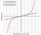
This is true, and is directly related to the square-law distortion in the force equations.
Attached figure compares relative force on the diaphragm as it is moved back and forth in the gap with zero stator signal.
This illustrates that in the constant voltage mode the diaphragm needs to stay within +/-20% of the center position to avoid rising distortion.
Your comment that the peak current can be much higher compared to the constant charge case is also true, but in general is not a concern. The reason is that the diaphragm(foil) only approaches the stators at low frequencies(<500hz) where the capacitive impedance is quite large so current magnitude thru the increased capacitance is still quite small. In fact at these frequencies the primary inductance of the transformer tends to be the dominate factor in the load impedance the amplifier sees.
Attachments
I've been a big fan of direct-drive ESL amps. My impression is that some transformers in some settings are excellent (like inter-stage coupling). But here is a theoretical question I have:
is there any reason why you couldn't make a transformer play say, 500-2000 Hz absolutely identical to the way a direct-drive amp played it? Would a transformer (esp. a "real world" transformer) always have some shortcoming arising from the nature of being a transformer device?
Ben
is there any reason why you couldn't make a transformer play say, 500-2000 Hz absolutely identical to the way a direct-drive amp played it? Would a transformer (esp. a "real world" transformer) always have some shortcoming arising from the nature of being a transformer device?
Ben
- Status
- This old topic is closed. If you want to reopen this topic, contact a moderator using the "Report Post" button.
- Home
- Loudspeakers
- Planars & Exotics
- Beveridge vs Final ESL Configuration