Those are for the body diode according to the LTspice help file. I imagine the parameters are based on the datasheet or some short measurements since the body diode won't affect anything on an audio amp.
Last edited:
Ahem... sorry for the previous post. Figured it out by reading some more. 🙄
Bob: you may be interested to know I made some IRFP240 measurements of my own and got Id results very close to the Ckst model at the lower end... until it gets to the "knee" around 1 amp. Contact me via PM and I'll be happy to forward the Id vs Vgs table.
Excellent!
Will do.
Cheers,
Bob
Please don't forget to note down the manufacturer of the transistor that the curve is taken from. Bob's model may be accurate for a different factory.
Hi K.
I have been at work on LTSpice models for the IXYS heavy duty power FETs.
Finished except for the capacitance of the body diode that sets Cds.
I have some idea but would like more, on the derivation of M and Vj, and what is the impact of N?
Do you have any comments on this, or was it done by Ian or Bob?
Best wishes
David
It bothers me that I can't comment on the effects of those parameters specifically. But usually I just run a stepped simulation and the relationships become obvious - that is usually as fast or faster than looking it up. It's true that you can confuse yourself this way when parameters interact, but in practice it just makes you smarter as you figure things out.
Those are for the body diode...since the body diode won't affect anything on an audio amp.
This was my initial reaction too, but it's not correct.
True that the body diode forward conduction should not matter in an audio amp, unless there's a transient from overload protection, say.
But this is not a reason to skip all the body diode parameters, because the reverse biased diode capacitance determines the Cds and this may matter.
I was alerted to this when I wondered why Bob's model had some parameters for the supposedly "unimportant" body diode.
It bothers me that I can't comment on the effects of those parameters specifically. But usually I just run a stepped simulation and the relationships become obvious...
Yes, I often overthink a problem, so I like to discuss with people who take the complementary approach, but sometimes it helps to know the theory so as to know what needs to be simulated.
I understand M and Vj as part of the capacitance curve fit, but I expect N should only influence the forward conduction, which is unimportant for audio.
So why is it included? It seems odd to include just one forward conduction parameter but not make the others correct.
Bob?
Best wishes
David
Most of us who make models leave in some vestigial parameters from the source materials if we don't like to rely on the LTspice defaults. Can you state what exactly is the discrepancy you're seeing? What other parameters? I did not have my hands on all the modeling work.
As for the body diode capacitance, Ian did indeed use it to make the capacitance behavior as accurate as he could; the VDMOS model doesn't work 100% for capacitance, so you have to make a call. Maybe the forward body diode parameters weren't given much attention.
As for the body diode capacitance, Ian did indeed use it to make the capacitance behavior as accurate as he could; the VDMOS model doesn't work 100% for capacitance, so you have to make a call. Maybe the forward body diode parameters weren't given much attention.
Last edited:
Most of us who make models leave in...
Yes, I see this often but I like to know why a parameter is included.
Then, if I see an unexpected parameter, I know there is some interaction I have not considered.
Random or arbitrary leftover "junk" makes it hard to know what is important to check.
Can you state what exactly is the discrepancy...
Not exactly a discrepancy but the values look unusual.
- M=0.75 where M is an exponent to model the way the junction is doped.
The default value for M is 0.5 for a step junction and typically it reduces towards 0.33 as diffusion makes it smoother. Only a hyper-abrupt junction would have the physical value more than 0.5.
Possible the MOSFET structure acts as a hyper-abrupt diode, I suppose.
- Vj=5 or 2.5 where Vj is the contact potential.
The default is 1 (V) and I would expect this not to vary too much because it is tied to the properties of the silicon, it depends on how the transistor is doped, not sure exactly how much variation is reasonable but 5 V seems remarkable.
- N=2.4 for Bob's models.
The default is 1 and it increases as the diode is less than ideal, 2.4 seems extraordinarily non-ideal.
It seems that attempts to fit the data have resulted in numerical values for parameters that correspond to a transistor that is physically unrealistic.
That can occur if the inevitable measurement inaccuracies interact badly with the sensitivities of the various parameters.
It produces a model that is not robust, fails badly outside a narrow domain of values.
I prefer a model with physically plausible parameters, even at the expense of a minor reduction in the apparent fit of the data.
Best wishes
David
Last edited:
One thing I can say is that the 0Vgs drain current is non-zero, and it depends on subthreshold conduction along with whatever else. People might think it is reverse diode leakage and use the diode parameters to add it. At one point we also had the problem where 0Vgs drain current was too high, like 5mA, despite the curves appearing to have a good fit. In fact the Exicons do draw mA of current at 0Vgs, but this current comes straight out of the exponential subthreshold curve, and diode leakage would be the wrong way to model it.
... In fact the Exicons do draw mA of current at 0Vgs...
Those were your measurements? And Ian used your data or did his own?
Just want understand what is independently measured and what is copied, not subject to a cross check.
I promised Toni some models, want to make them the best I can.😉
Best wishes
David
I seem to remember measuring it with a 9V battery and current meter. We did not focus on getting 0Vgs drain current perfectly right, the focus was on getting the curve harmonically accurate compared with digitized (EDIT: measured) data and then the other parameters kept in a reasonable range. You can't do all at once, but you can get it reasonably good with VDMOS.
Last edited:
Here is what Ian had to say.
Ian Hegglun said:Jigs for gate charge and body diode fitting are attached and you can post these on the thread (or PM them if you prefer). Zip includes the Datasheet I used for extracting all the parameters.
One thing about the body diode is that under normal forward voltage operation it is reverse biased so the capacitance is fairly constant and relatively low. We could even merge its capacitance into the Cds parameter as long as Vds is positive. It's only when MOSFET's are used in their reverse region that the body diode parameters is important.
Another thing about the body diode model inbuilt into LTspice VDMOS is that it has no Is(Tja) parameter so the temperature dependency of the VDMOS diode is very wrong at high temperatures. You can see this in the body diode jig in the attachment at 150C -- compare it with the datasheet.
Adding Tja temp co for the body diode Is gives the correct temperature dependency of the body diode. Jig 2 for the body diode has Is=1n*(1+0.3*dTja).
To get the high current range better we add temp dependency to Rb which is the resistor in series with the body diode for the VDMOS in LTspice). Again this level of modelling of reverse current temperature dependency is really only relevant to a few special applications like synchronous rectifiers -- it's not relevant to audio amps.
Attachments
Here is what Ian had to say.
Some of Ian's quote is a bit odd too.
"One thing about the body diode is that under normal forward voltage operation it is reverse biased so the capacitance is fairly constant and relatively low. We could even merge its capacitance into the Cds parameter.."
There is no Cds parameter for the VDMOS model.
LTspice have removed it, unless it's there very undocumented.
That was more or less my point, that we need to consider the body diode, precisely because it is the only way to set Cds.
Best wishes
David
I will read the attachment and think some more, minor computer problem at the moment.
Last edited:
If you open the attachment you will see a comparison of the model to the data. When speaking on a topic this tedious, things don't always come out right. See if you find a flaw in the model and we can start there.
... on a topic this tedious...
I hope it's not been tedious, but it is rather fussy, easy to make mistakes, just as you imply.
So I didn't want to criticize or find flaws in your model, just understand better so I could do my own IXYS models as accurately as possible.
Thanks for the help
David
Last edited:
Hi K.
I have been at work on LTSpice models for the IXYS heavy duty power FETs.
...
Do you have any comments on this, or was it done by Ian or Bob?
David
Hi Dave,
You asked me (in another thread) to say something in this thread on better models in general.
I have been working with Keantoken for several years on subcircuits to improve the basic VDMOS model in LTspice.
We were about to make them public last year but the work stalled so I could write my Linear Audio Vol. 13 article (plus the building and debugging and getting PCB's made and debugged and then writing builder documentation and updating my web site). This has taken over the last 6 months. Now it's almost there I can get back to models.
So far we have fitted subcircuits for electrothermal plus quasisaturation parameters for Exicon 20N20, 20P20, 10N20, 10P20 lateral's. IRF640, IRF9640 (IRFP240/IRFP9240). The LND150, DN2530, DN2530 and DN2625 depletion MOFET's. The FDC6320n CMOS matched pair and the 7WU04, 74HCU04, and 4069 CMOS inverters for linear mode simulations.
The next step is documentation on using them and fitting parameters to datasheets.
Then I would like to get back to my PAK project which is to solve equations for amplifier structures like the Darlington and CFP, which are needed to solve equations for complete amplifiers. BTW my PAK project's (pending) equations could be used to improve the reliability and speed for convergence in SPICE simulations for amplifiers by making use of approximate solutions to point the numerical engine in the right direction to find the dc operating point. I am fed up with SPICE simulators often taking 'for ever' to find the operating point!
If you (or anyone reading this post) are interested in solving the Darlington and CFP equations then you can download it on my PAK site in the PAK User Guide 2012. CFP analysis is on p66 and the Darlington on p85. P91 gives a large signal solution for the differential pair, something that I have not see in the literature as far as I can find. There's even a section on current driven power output stages (p109-112) and why it is so linear.
Back to the LTspice VDMOS model. It is a very simple model that can model gate charge for MOSFET's quite well. But it does not have any temperature coefficients available to us which a big minus (there are internal fixed temp co's for Kp and Vto, but they can't be altered and their tempco is not in the documentation). That's why Keantoken and I use curly brackets to add tempco's to any of the parameters we need to. It is only intended as a work-around until the internal model code is improved.
Another thing the VDMOS does not model is the curved knee in the gds at pinchoff which is important for modelling FET's for soft clipping circuits like my Cube-law amplifier. This effect can be added using a subcircuit that in effect 'wraps around' or 'clips-on' to the existing VDMOS model and adds extra effects. And if you find the effect doesn't make make a difference you can easily drop the subcircuit and just use the basic VDMOS to speed up simulations.
So you don't need to start over again to fit the extra parameters when you want to add say quasisaturation. It's the same again for adding electrothermal effects. Electrothermal effects are useful for simulating Vbe bias stability when you turn on the power to the amp you can plot the junction temperature change with time and the idle current at the zero crossings and I did this for Bob Codell's amplifier circuit in his download area. And if you find this effect doesn't make make a difference then you can easily drop the subcircuit for faster simulations.
The simulation times with electrothermal plus quasisaturation effects added to the VDMOS are quite reasonable; usually 5-10 seconds of real time for a few cycles of simulation time, or about 10 times slower than with no electrothermal effects. I'm really pleased about that. It's reasonably fast compared to my earlier electrothermal models thanks, to Keantoken's idea of interpolating between two fixed temperature VDMOS models using a Behavioural current sources to do the interpolation calculations. We also added electrothermal effects to the BJT model.
I hope that is useful info.
What other problem areas are you thinking about?
Last edited:
So far we have fitted subcircuits for electrothermal plus quasisaturation parameters...
I did not use sub-circuits, I attempted to model the sub-threshold behavior with the use of the Ksubthres parameter and tune the other parameters.
I am not very experienced with MOSFETs so I am not sure about quasi-saturation in a MOSET context.
It appears to involve MTRIODE, how does it relate to sub-threshold conduction parameters?
Back to the LTspice VDMOS model. It is a very simple model that can model gate charge for MOSFET's quite well. But it does not have any temperature coefficients available to us...
It has XTI body diode temperature coefficient available, but not very useful for audio applications.
Another thing the VDMOS does not model is the curved knee in the gds at pinchoff which is important for modelling FET's for soft clipping circuits like my Cube-law amplifier. This effect can be added using a subcircuit that in effect 'wraps around' or 'clips-on' to the existing VDMOS model and adds extra effects.
Isn't this basically what Ksubthres is for?
What other problem areas...
After my initial post that you quoted there is a bit of discussion with Keantoken on "the derivation of M and Vj, and what is the impact of N?"
Perhaps you could read and comment?
Best wishes
David
The PAK stuff is new to me, may take a while before I can comment sensibly.
Last edited:
After my initial post that you quoted there is a bit of discussion with Keantoken on "the derivation of M and Vj, and what is the impact of N?"
Perhaps you could read and comment?
I'll reply to this first (others in another post).
I used Bob's values as a starting point. Then, if I find the plots are not like the data sheet then either try altering the values or enhancing the model. I think Bob has started by looking at existing models, eg Vishay model (31 Oct 1999) body diode (MD2) has Is=5e-9, N=1.4, Vj=5, m=0.87. Note that has Vj=5.
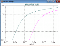
Use a Jig that plots Ids versus Vgs. Keantoken posted my jig for the IRF640 in this post. This does not show changes in Vj (a capacitance parameter) only Is and N (also Rb the VDMOS body diode series resistance).
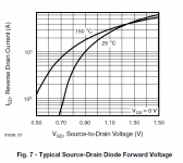
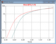
The plots for the standard VDMOS body diode at Tj=25C and 150C are attached. The left plot is 25C and the right 150C. Compare this to the datasheet plot Fig 7 (attached) and you can see the VDMOS has the 150C on the wrong side! It's completely wrong because the VDMOS doesn't have the right tempco for Is parameter (probably the default is no tempco for Is). You can see this by adding a tempco for Is using curly brackets gives the right curves (see attached Jig2). Jig 2 model follows:
*VDMOS with subthreshold (c) Ian Hegglun and Keantoken Jun 2016
.model IRF640-Tja_ VDMOS (Rg=5 Vto={4.30-6m*(Tja+temp-25)} Lambda=3m
+ Rs={35m*(1+3.5m*(Tja+temp-25))} Kp={13.0/(1+8.8m*(Tja+temp-25))}
+ Ksubthres={0.23*(1+4m*(Tja+temp-25))} Mtriode={0.35} Rd={0.1*(1+5m*(Tja+temp-25))}
+ Cgdmax=2600p Cgdmin=10p a=0.35 Cgs=1250p Cjo=3000p Tnom=temp
+ m=0.75 VJ=5 IS={1n*(1+0.3*(Tja+temp-25))} N=1.3 Rb={0.01*(1+2.5m*(Tja+temp-25))}
+ Vds=200 Ron=0.15 Qg=67nC mfg=IHKT1703)
I don't have a jig for plotting the body diode capacitance. As I suggested (in the earlier post) the body diode capacitance variation with Vds is not very important to get perfect. Most of the drian-source capacitance variations are set by the VDMOS parameters Cgdmax, Cgdmin, a=0.35, Cgs and Cjo. A jig available for fitting these parameters on the web here. I'll attach my jig used to fit the IRF640 caps.
Attachments
Read the Electronics World "Hotter Spice" available in "IansArticles" on myDrive. The link is now in my Sig line below.I did not use sub-circuits, I attempted to model the sub-threshold behavior with the use of the Ksubthres parameter and tune the other parameters.
... I am not sure about quasi-saturation in a MOSET context. It appears to involve MTRIODE, how does it relate to sub-threshold conduction parameters?
...
It has XTI body diode temperature coefficient available, but not very useful for audio applications.
P16 shows the quasisaturation region for lateral MOSFET's. Real measured gds curves can be seen in the "Simple Curve Tracer" panel (p3) in the oscilloscope display, which is pasted in from a DSO printout.
Gds is plotted using Vds sweep with a constant (or stepped) Vgs. A gds plot is generated using Vgs sweep with a constant Vds. These plots need to be fast and to avoid thermal effects from start to finish of the plot, and a low duty cycle to avoid an excessive Tj. It's hard to do a Tj=25C plot if your ambient temperature is close to 25C unless you use a very low duty factor. I built a jig recently to accurately test Exicon laterals for VDMOS models. It took a bit of effort but I got about 1% accuracy (repeatability) for measurements. I used a S/H and a 4 digit DMM. Then plotted the points in a spreadsheet. Then I exported to LTspice Tables for fitting in a jig. I haven't documented the bench test jig.
Mtriode in the Ltspice VDMOS is not documented and I haven't seen any equations for it. It appears to be a power-law curve fitting parameter. It doesn't allow (accurate) fitting of the quasisaturation region in Exicon lateral's or CMOS inverter FET's.
Subthreshold conduction is for fitting the low Vgs region with sufficient Vds (eg Vds>Vto+1V). Mtriode is for fitting Rds(on) for low Vds (eg Vds<Vgs-Vto) with moderate for saturation Vgs (eg Vds> Vgs-Vto +1V).
As far as I can find out "Pinchoff" has different meanings for jFET's and MOSFET's. I have never found anyone explaining this; maybe because jFET models developers live in a different world to MOSFET modeller's? As far as I understand, 'pinchoff' for a jFET is when the gate voltage turns off drain current -- so it's the threshold voltage. For a MOSFET pinchoff is defined as when the gate-source drive voltage exceeds the drain-source voltage, where 'gate drive' is the effective gate voltage after subtracting the threshold voltage. I'm self-taught in this area -- FET modelling wasn't part of my course materal back in 1976. Maybe someone who knows can explain pinchoff and how it's meaning differs for jFET's and MOSFET's?
Re XTI in the VDMOS (tempco for the Is parameter). Thanks. I never noticed that. If it works then we can use it instead of the curly bracket method.
- Home
- Design & Build
- Software Tools
- Better power MOSFET models in LTSpice