sippy, any chance you could snap a picture of your betaLTA with the plugs, tweeters, socks etc. I've been interested in what the LTA's can do and what you've done sounds like a good idea. I get the gist of it but am not quite clear.
Sure, but I'll have to scare up a camera..... mine died and post pics later.
The sock is basic, the felt is about 2mm thick, the cut dimensions are 60mm x 138mm (44mm x 3.142), rolled longest dimension and held together inside with a strip of hi-tack masking tape. The sock slips over the plug down to the protruding bit of the VC former - I could not be bothered to sew the seam, though will do eventually as it will be far neater.
The sock is basic, the felt is about 2mm thick, the cut dimensions are 60mm x 138mm (44mm x 3.142), rolled longest dimension and held together inside with a strip of hi-tack masking tape. The sock slips over the plug down to the protruding bit of the VC former - I could not be bothered to sew the seam, though will do eventually as it will be far neater.
A rough pic can be seen here: http://www.diyaudio.com/forums/full-range/65061-full-range-speaker-photo-gallery-236.html#post3416654
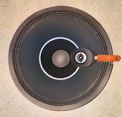
I got the 12LTAs. I already cut of the dust caps (also removed the surrounds of them after cutting the center off so the edge of the voice coil shows completely!).
The impedance plot's resonances (very zoomed in) seemed to stay the basically same, in normal view they were almost indistinguishable. Nevertheless, one CAN see that the dips at 600Hz, 1,3khz, 1,6khz and 3khz are slightly less pronounced without the dust cap, meaning the resonances behave little better. On the other hande the two upper resonances at ~4,5kHz and 5,5khz are slightly more pronounced. This is at least how I read the graphs.
The measurement was performed without any phase plug (and with only ~30min burn in). With a phase plug things will look somewhat different I presume. I will make new measurements later.
The green is without the dust cap:
I also made a quick hack testing the shorting ring I had in mind. I made it out from ~49-50mm wide wood puck I cut, and put one layer of aluminum tape around it. This already shoved some difference, meaning that the inductance dropped little. I will make more measurements after I get the full aluminum pucks/knobs, I think they will have greater impact (as would fully aluminum phase plug).
The green is with the (mock of a) shorting ring:
By the way the absolute reading are off for some reason with my new sound card (even after calibration and double checking the resistor's value etc), so do not look at absolute reasings, only look at the relative differences.
And by the way, these are excellent sounding fullrangers! 12LTA smokes the Beyma 12GA50s.
An externally hosted image should be here but it was not working when we last tested it.
The impedance plot's resonances (very zoomed in) seemed to stay the basically same, in normal view they were almost indistinguishable. Nevertheless, one CAN see that the dips at 600Hz, 1,3khz, 1,6khz and 3khz are slightly less pronounced without the dust cap, meaning the resonances behave little better. On the other hande the two upper resonances at ~4,5kHz and 5,5khz are slightly more pronounced. This is at least how I read the graphs.
The measurement was performed without any phase plug (and with only ~30min burn in). With a phase plug things will look somewhat different I presume. I will make new measurements later.
The green is without the dust cap:
An externally hosted image should be here but it was not working when we last tested it.
I also made a quick hack testing the shorting ring I had in mind. I made it out from ~49-50mm wide wood puck I cut, and put one layer of aluminum tape around it. This already shoved some difference, meaning that the inductance dropped little. I will make more measurements after I get the full aluminum pucks/knobs, I think they will have greater impact (as would fully aluminum phase plug).
An externally hosted image should be here but it was not working when we last tested it.
The green is with the (mock of a) shorting ring:
An externally hosted image should be here but it was not working when we last tested it.
By the way the absolute reading are off for some reason with my new sound card (even after calibration and double checking the resistor's value etc), so do not look at absolute reasings, only look at the relative differences.
And by the way, these are excellent sounding fullrangers!
12LTA smokes the Beyma 12GA50s.
Last edited:
I've become convinced since my last post that the bullet shape phase plug is only for vanity.
IMHO might as well make it 45mm dia parallel and wrap it with the thin craft felt.
Legis, I have no way of measuring drivers so improvements are down to what sounds 'good' or 'bad' for me and will be following your findings closely 🙂
IMHO might as well make it 45mm dia parallel and wrap it with the thin craft felt.
Legis, I have no way of measuring drivers so improvements are down to what sounds 'good' or 'bad' for me and will be following your findings closely 🙂
Oh, 30mins running is nothing to these drivers, mine started to calm down a little after about 200 - 300hrs and several thrashings.
By the way, as the whizzer of the 12LTA is already very rigid, has anyone tried douping it with shellac, dammar or something similar? This might be not be a bad move. I might at least treat the outer rim like it's treated in the "Super 12".
"The edge damping on the free (whizzer) cone is precipitated chalk in a polymer base to reduce edge interaction."
tip18
"The edge damping on the free (whizzer) cone is precipitated chalk in a polymer base to reduce edge interaction."
tip18
By the way #2, the plug I used to test the shorting ring a bit, is 49,6mm in diameter and 21mm thick and was just able to get in there without touching the VC on the sides. The depth of the VC cavity in 12LTA is ~24,5mm. This is according my digital calipers.
So the 48mm x 22mm volume knobs I linked before, are almost perfect match. The 12LTA actually looks quite nice with a plug that just fills the cavity, and does not sound bad either.
Picture there almost mirror-like shine polished aluminum puck without the center hole
 :
:

So the 48mm x 22mm volume knobs I linked before, are almost perfect match. The 12LTA actually looks quite nice with a plug that just fills the cavity, and does not sound bad either.
Picture there almost mirror-like shine polished aluminum puck without the center hole
I did some quick distortion measurements (with unoptimal measuring equipment like EMC8000 condenser mic, those always distort itself) comparing voltage drive and current drive. This driver responds very well to current drive. The voltage ration was 9:1 in current drive, so it can reduce harmonics about 19dB at maximum compared to voltage drive.
The mic was ~1,6m away, slightly off-axis. I did not match the responses, but comparison is pretty easy still. In picture one, the level is almost the same at higher frequencies. In second picture the low and middleband is pretty much matched.
Current drive on the right (unequalized responses).
And unequalized frequency response ~35-40cm away, on axis. Current drive on the right.
The measurements were done without any phase plug.
The mic was ~1,6m away, slightly off-axis. I did not match the responses, but comparison is pretty easy still. In picture one, the level is almost the same at higher frequencies. In second picture the low and middleband is pretty much matched.
Current drive on the right (unequalized responses).
An externally hosted image should be here but it was not working when we last tested it.
An externally hosted image should be here but it was not working when we last tested it.
And unequalized frequency response ~35-40cm away, on axis. Current drive on the right.
An externally hosted image should be here but it was not working when we last tested it.
The measurements were done without any phase plug.
An externally hosted image should be here but it was not working when we last tested it.
Last edited:
I made somem ore distortion measurements regarding voltage and current drive with Beta 12LTA. Driver is in ~35cm wide OB, mic 1m away from the driver on axis.
By clicking the lkinks one can see the spectrum of the measurement. Current driving reduces total harmonic distortion and in majority of cases cleans up the spectrum's higher order (>H3) harmonics. It will be interesting to see if the shortin ring linearizes the driver even further!
Regarding the heard sound, there is no comparison between the current drive and the voltage drive. I really recommend to current drive this transducer. Current drive + tubed amp might work heavenly!
I'm greatly fond of this driver, it does some things very close to the ESL's.
Frequency Hz
Level dB: Voltage drive THD % / Current drive THD %
50Hz
90dB: Voltage drive 12,4% / Current drive 8,73%
100hz
90dB: Voltage drive 1,81 % / Current drive 0,978 %
95dB: Voltage drive 3,65 % / Current drive 2,01 %
200Hz
90dB: Voltage drive 0,375 % / Current drive 0,252 %
95dB: Voltage drive 0,674 % / Current drive 0,487 %
400Hz
90dB: Voltage drive 0,181 % / Current drive 0,0644 %
100dB: Voltage drive 0,360 % / Current drive 0,111 %
800Hz
90dB: Voltage drive 0,202 % / Current drive 0,0541 %
95dB: Voltage drive 0,296 % / Current drive 0,0665 %
100dB: Voltage drive 0,572 % / Current drive 0,116 %
1600Hz
90dB: Voltage drive 0,485 % / Current drive 0,197 %
95dB: Voltage drive 0,879 % / Current drive 0,256 %
100dB: Voltage drive 1,78 % / Current drive 0,414 %
3200Hz
90dB: Voltage drive 0,401 % / Current drive 0,201 %
95dB: Voltage drive 0,758 % / Current drive 0,387 %
6400Hz
90dB: Voltage drive 0,092 % / Current drive 0,0968 %
95dB: Voltage drive 0,175 % / Current drive 0,184 %
100dB: Voltage drive 0,357 % / Current drive 0,314 %
What amp do you use to provide current drive?
I actually used 2 x 33 ohm series resistors, which gives me about 9:1 voltage ratio with 8 ohm driver and thus has potential to reduce the harmonics by ~19dB at maximum (depends on driver how much it benefits from current drive).
Normally this would make the driver very unsensitive but I use 1:4 step-up transformer so the voltage sensitivity is only reduced by ~6dB and one can still blast the hell out of the drivers. The resulting impedance, the amp sees, is approx. ~5ohms.
Sensitivity could be increased further by increasing the step-up ratio, but the load would be more difficult. Also the voltage ratio could be reduced by dropping the series resistance, to gain more sensitivity, but it would not propably linearize the driver as much.
High driver sensitivity definitely helps when using current drive this way! It has the benefit that one can use all normal amps to realize the current drive.
Also First Watt F1 or something similar would propably be nice amp, that does the current drive "naturally".
hello - what is the VA rating and any particulars on your stepup transformer used in the tests? perhaps there's an on-shelf unit suitable for experimentation.
hello - what is the VA rating and any particulars on your stepup transformer used in the tests? perhaps there's an on-shelf unit suitable for experimentation.
Hi, the core is specified 50VA (core's area ~11,5cm2), core material is grain oriented silicon steel (Bmin = 1.7T). 2 x 30 turn bifilar wound primaries (2,0mm2 wire), 2 x 120 turn bifilar wound secondaries (0,44mm2 wire). Right now I'm using the trafo with both primaries and secondaries connected in parallel to get 1:4 step-up, 1:2 and 1:8 are also possible.
I actually used 2 x 33 ohm series resistors, which gives me about 9:1 voltage ratio with 8 ohm driver and thus has potential to reduce the harmonics by ~19dB at maximum (depends on driver how much it benefits from current drive).
Normally this would make the driver very unsensitive but I use 1:4 step-up transformer so the voltage sensitivity is only reduced by ~6dB and one can still blast the hell out of the drivers. The resulting impedance, the amp sees, is approx. ~5ohms.
Sensitivity could be increased further by increasing the step-up ratio, but the load would be more difficult. Also the voltage ratio could be reduced by dropping the series resistance, to gain more sensitivity, but it would not propably linearize the driver as much.
High driver sensitivity definitely helps when using current drive this way! It has the benefit that one can use all normal amps to realize the current drive.
Also First Watt F1 or something similar would propably be nice amp, that does the current drive "naturally".
Thanks for explanation. I was thinking you might have a transimpedance power amp as rare as they are. Do you use the step up transformer before the series resistor?
Thanks for explanation. I was thinking you might have a transimpedance power amp as rare as they are. Do you use the step up transformer before the series resistor?
Yes they are after the trafo. Transformers usually like to be driven from low impedance, adding resistance before the trafo might increase distortion.
At some point I thought about building First Watt F1 but never got to it. At some point I might, or maybe some tubed transconductance amp!
Freddi, if you are going to use the transformer full range, it should have enough turns on the primary and big enough core area to be able to handle bass frequencies without saturation and distortion. High passed signals are much easier for the transformer.
Here is a formula to predict transformers saturation point: http://www.diyaudio.com/forums/planars-exotics/161485-step-up-transformer-design-4.html#post2096503
My present trafos handle around 9-10 volts @ 50Hz with primaries in parallel, and 18-20V primaries in series (2x30turns PRI on 11,5cm core).
Here is a formula to predict transformers saturation point: http://www.diyaudio.com/forums/planars-exotics/161485-step-up-transformer-design-4.html#post2096503
Bmax = E x 10^8 / (4.44 x f x N x A)
Bmax = Peak AC flux density in core (Gauss)
E = Applied voltage in Vrms
f = frequency
N = number of primary turns
A = core area cm^2
Note that Bmax is inversely proportional to the number of primary turns.
Typical Bmax for modern transformer iron is about 12,000 gauss at the onset of saturation
My present trafos handle around 9-10 volts @ 50Hz with primaries in parallel, and 18-20V primaries in series (2x30turns PRI on 11,5cm core).
Last edited:
- Status
- Not open for further replies.
- Home
- Loudspeakers
- Full Range
- Beta 12LTA in a 3cf box - port size