There's no question in my mind that the magnetic field of a permanent magnet and an electromagnet will interact, and that there will be higher order effects (the electromagnet will influence the field/domains of the permanent magnet and vice versa) resulting from this interaction. This is considering the EM field as a whole and the transfer of energy not being a perfect process, rather than an examination of the superposition of the two fields.EC8010 said:It strikes me that if a loudspeaker voice coil opposes the static flux in the gap in oder to produce a force, surely the instantaneous flux in the gap is changing? And if the pole pieces are a magnetic short-circuit (in order to get all the energy from the magnet into the gap), and the magnet is a permanent magnet, something has to give? Is it perhaps the magnetic equivalent of two Thevenin sources fighting one another via their internal resistances?
John Watkinson is a F.A.E.S., so it's true. In this series, he was being deliberately provocative, calling loudspeaker design a subset of carpentry.😀
He was trying to inspire original thinking by pointing out the inadequacies of current technology, of which the magnetic circuit is a part. It was a very interesting series, but nothing to get too worried about.😉
He was trying to inspire original thinking by pointing out the inadequacies of current technology, of which the magnetic circuit is a part. It was a very interesting series, but nothing to get too worried about.😉
He states that the modulation is a by - product of producing a force, so if you cancel the modulation, you also cancel the force.
IMHO, the Watkinson principle isn't a huge hurdle. Circlotron mentioned counter-current--that's one workaround, but it costs you some efficiency.
Here's another exception from the musty files of my transducer-design archives: a siamese-twinned bipolar driver topology I originally called Flux Fulcrum. 😎
Two horizontally opposed VCs/cones share a twin-gap motor. Their net field deflections cancel, and you don't lose any efficiency.
I also have another design that incorporates coil inductance cancellation, if you can picture that. 🙂
It would be interesting to compare this with a standard topology driver in terms of Barkhausen phenomena.

Bill F. said:
I originally called Flux Fulcrum. 😎
Two horizontally opposed VCs/cones share a twin-gap motor. Their net field deflections cancel, and you don't lose any efficiency.
IIt would be interesting to compare this with a standard topology driver in terms of Barkhausen phenomena.
I think the only reason normal drivers have been around for so long is they are easy and cheap to make, This kind of driver would be very very difficult make, but i would love to hear a pair in action, if any one has a pair let me know, you have found a buyer!
...I don't think you'll have much luck finding a Flux Fulcrum out there... AFAIK, it's my own original design, and I never manufactured any. Sorry if I wasn't clear in my prev. post. 🙂
Oh Bill ya Big teaser!Bill F. said:...I don't think you'll have much luck finding a Flux Fulcrum out there... AFAIK, it's my own original design, and I never manufactured any. Sorry if I wasn't clear in my prev. post. 🙂

I think as this design as has 2 cones it would have a a good LF output, I try and make one to see what happens, how the hell do i join 2 cones to one bobbin with 2 windings in a open magnetic system?
That would be an interesting design for dipole applications...
Well, you'd have to put it in a Linkwitz Phoenix-style baffle to make it into a dipole...
It is necessarily a push-push bipolar radiator. If you swap phases on half of it to make it a dipolar radiator, you lose the whole Flux Fulcrum effect. You'd basically have an open ended Differential Drive topology.
I think as this design as has 2 cones it would have a a good LF output
As a bipole, at least it'll have no baffle step. 🙂
I try and make one to see what happens, how the hell do i join 2 cones to one bobbin with 2 windings in a open magnetic system?
I don't have a patent or anything, so Godspeed!
I always pictured it working best with a larger front-mount ring on one end and a smaller rear-mount face on the other, so you feed the driver through a larger hole on the front of the cabinet and butt it up to a smaller hole on the rear.
Shouldn't be too difficult to create the motor. Just have to figure out the easiest way to suspend the pole in the gaps--maybe make it in two halves and bolt it together.
Paradise_Ice said:I think the only reason normal drivers have been around for so long is they are easy and cheap to make...........
Yup -
this is the reason that "normal drivers" superseded field coils, and the reason that field coils are currently only manufactured in France and have such a limited distribution
Field coils solve _ some_ ( a lot? ) of the problems mentioned in this thread -
Regards
Ken L
Ah, didn't realize at first glance that the cones weren't directly coupled and were in phase instead of out of phase.
Well... if bipolar is your thing I suppose this would be nice. Though subs don't generally benefit quite as much from the SOTA low distortion driver technologies (well, the numbers benefit just as much if not more than midranges, but the audibility of improvements is diminished in that frequency range), this would at least make an interesting opposed force dual sub driver mounting.
Or is it a single sub... ?
Yeah, I agree the Flux Fulcrum would likely be over the top for a sub. I don't know for sure, but I suspect Barkhausen noise would manifest somewhere above mid-bass, if only because our hearing is more acute there.
I actually conceived this bipole driver to be mid/wide-range. Bipole mids can be a slick answer to several monopole shortfalls like baffle step and falling power response. Some also claim unsubtle improvements in diverse points of enclosure radiation, imaging, etc. from the newtonian force cancellation of solidly coupled bipolar drivers.
But if you're not into bipoles, there's always the counter-current trick, but it'll cost you about 3dB. Still, it's certainly the easiest way to do a Barkhausen A/B comparo.
Ok, I feel more than a little dumb. 
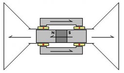
I just realized my previously posted pic is a flawed early concept drawing of my Flux Fulcrum design. It's been a while since I came up with this concept, and I briefly forgot the conclusion to my own thought experiment! Though the driver previously pictured would operate with opposing newtonian forces, obviously it would tend to deform the B field just like any other common driver since the coils are wound in the same direction--Duh! 🙄
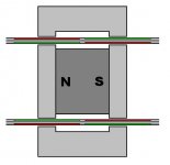
So please disregard the previous pic and consider the one below instead--it's what I meant to post before. It's a bipolar motor that functions like two superimposed Differential Drive motors. Part of my design goal was also to achieve rising motive force with excursion by harnessing the attractive forces between concentric coils wound in the same direction. This might be matched with a suspension of corresponding rising rate to net a constant signal/excursion ratio.
Another obvious point I failed to remember in my earlier posts is that the Differential Drive topology (JBL is a licensee) accomplishes inductance cancellation by driving two antiphase series coils. So IMO it would theoretically exhibit substantially less Barkhausen distortion than a garden variety motor of identical specs.
Because of their reduced flux modulation, I have also wondered if balanced topologies like countercurrent, DD, Flux Fulcrum (and perhaps current-source-energized field coils, though not balanced) exhibit noticeably less dynamic compression of the leading edge of heavy transients--likely much more audible than Barkhausen distortion.
I just realized my previously posted pic is a flawed early concept drawing of my Flux Fulcrum design. It's been a while since I came up with this concept, and I briefly forgot the conclusion to my own thought experiment! Though the driver previously pictured would operate with opposing newtonian forces, obviously it would tend to deform the B field just like any other common driver since the coils are wound in the same direction--Duh! 🙄
So please disregard the previous pic and consider the one below instead--it's what I meant to post before. It's a bipolar motor that functions like two superimposed Differential Drive motors. Part of my design goal was also to achieve rising motive force with excursion by harnessing the attractive forces between concentric coils wound in the same direction. This might be matched with a suspension of corresponding rising rate to net a constant signal/excursion ratio.
Another obvious point I failed to remember in my earlier posts is that the Differential Drive topology (JBL is a licensee) accomplishes inductance cancellation by driving two antiphase series coils. So IMO it would theoretically exhibit substantially less Barkhausen distortion than a garden variety motor of identical specs.
Because of their reduced flux modulation, I have also wondered if balanced topologies like countercurrent, DD, Flux Fulcrum (and perhaps current-source-energized field coils, though not balanced) exhibit noticeably less dynamic compression of the leading edge of heavy transients--likely much more audible than Barkhausen distortion.
Attachments
Bill F. said:Ok, I feel more than a little dumb.
I just realized my previously posted pic is a flawed early concept drawing of my Flux Fulcrum design. It's been a while since I came up with this concept, and I briefly forgot the conclusion to my own thought experiment! Though the driver previously pictured would operate with opposing newtonian forces, obviously it would tend to deform the B field just like any other common driver since the coils are wound in the same direction--Duh! 🙄
So please disregard the previous pic and consider the one below instead--it's what I meant to post before. It's a bipolar motor that functions like two superimposed Differential Drive motors. .
Dont i feel silly, i showed your design to my friend Henk Vos and he told me this would not work, I put the points made by you to him and got upset with me! He is an old gent with a short fuse! and i was in the blast zone, looks like i have to apologies now, oh God Bill, you better by me a drink one day
 !, I had a feeling i was wrong but my big mouth just kept on yapping, I understand the whole concept now! round 2, and if i come back with a bloody nose again you owe me 2 drinks Bill,
Sorry to pull you into my web of absentminded deceit, 'dise! 🙁
I hope you're able to mend the rift with your ol' pal, but he may not like this version, either--it's pretty "out there."
P.S.--the previous version would indeed function, just not with the balancing fields as advertised.
I hope you're able to mend the rift with your ol' pal, but he may not like this version, either--it's pretty "out there."
P.S.--the previous version would indeed function, just not with the balancing fields as advertised.
I believe that hysteresis losses, which result from shifting of the magnetic domains, were previously described. Eddy current losses will also play a role in sound quality of a speaker. Eddy current losses are inversely proportional to the resistance of the material in which the eddy currents are flowing. Although most magnets do have high electrical resistance, their resistance is not infinite.
As alternating current is driven through the speaker's voice coil, it will stimulate eddy currents in the magnet, but even higher eddy currents in the pole piece. These eddy currents will add to the power losses of the speaker. As with hystereses losses, these losses will increase with frequency. Thus, when high frequency transients are applied to the speaker, a greater portion of the energy will be absorbed by the pole piece and the magnet in comparison to low frequency signals.
Although I have not performed sound quality testing with magnets or pole pieces, I would expect that a magnet made with a higher resistance material would sound better than a magnet having a lower resistance, but that is otherwise equivalent. Nevertheless, I would expect a pole piece having a high electrical resistance to be even more beneficial, assuming you can still maintain the desired level of magnetic flux.
I would expect that a magnet made with a higher resistance material would sound better than a magnet having a lower resistance, but that is otherwise equivalent.
This is some of the fundamental thinking behind ATC's excellent studio drivers--they line the inner face of the top plate and outer face of the pole with the coyly named SLMM (super-linear magnetic material) that couples low reluctance with high electrical resistance, effectively suppressing eddy currents, which otherwise tend to form largely on the gap surfaces.
However, the completely opposite technique of using copper sheathing to maximally conduct eddy currents (without hysteresis) is also effective at reducing distortion since it, too, shields the ferromagnetic return circuit from fluctuating fields and resulting hysteretic eddy currents. The downside can be too much damping pushing Qes too low.
Either way, the whole name of the game is to avoid magnetic hysteresis by keeping any ferromagnetic material from conducting eddy currents.
I lay awake in bed last night thinking about this and came to the same conclusion! I think it would still work though if instead you phased the drive to the two coils so the cones worked as an isobaric pair. Not clamshell method but butt-to-butt method but with no butt.Bill F. said:Though the driver previously pictured would operate with opposing newtonian forces, obviously it would tend to deform the B field just like any other common driver since the coils are wound in the same direction--Duh! 🙄
Not only that, I think I know a way where you could try this out using a pair of conventional unmodified drivers and a small amount of external polepiece trickery. I'll get busy and draw a picture...
Here we go! Get a a pair of identical drivers and make sure the rear polepieces are nice and smooth so they make good contact. Then you have to put a steel (ideally tubular) polepiece from the periphery of the one front polepiece all the way to the other.
The idea is that both the magnet systems are in parallel but the voice coils are driven opposite phase so while one magnet is having it's field pushed one way the other magnet is getting the opposite treatment. The external polepiece transfers this rude behaviour across from one side to the other and hopefully the nett effect is zero. 🙂
The idea is that both the magnet systems are in parallel but the voice coils are driven opposite phase so while one magnet is having it's field pushed one way the other magnet is getting the opposite treatment. The external polepiece transfers this rude behaviour across from one side to the other and hopefully the nett effect is zero. 🙂
Attachments
- Status
- Not open for further replies.
- Home
- Loudspeakers
- Multi-Way
- Best Sounding Magnet!