Electra-Print. Have listened to more than one of his amps, all excellent.Jack ships all over the world.
Absolutely agree. I've been buying from Electra-print for years. Top quality and excellent service. Plus I got tons of valuable audio info from Jack.
It's reasonable enough to want to know which one is best and which to avoid, especially if you are ordering from far off places without having heard the transformer first, but can you really base a decision on the results of a test like the ETF's?
One person here praises a transformer eliminated in the first round, nobody mentions the R-core that made it to the semi-finals, and even reading the results in the linked pdf make it hard to tell how some were scored over others.
Distinguishing a finely engineered and built transformer of good materials from a coat hanger wound around a nail I can see, but once you get to the point where they're all basically standing on the same turf surely optimizing the circuit for the individual transformer needs to be considered. No?
First impression: nice but not better then any Tango / Tamura.
I guess copper loss is 0,4 -0,6 dB?
I hope you used a c-core otherwise coreloss will be unnecessary high.
I guess copper loss is 0,4 -0,6 dB?
I hope you used a c-core otherwise coreloss will be unnecessary high.
As I already said in other threads is very hard to evaluate audio transformers by looking at specs and measures.<snip>
I bought a pair of Lundahl LL1688 70mA SE OPT which was designed for use with the 845 tube recently. I could not wait and put them in my 300B mono. At first, I configured it with 5K to 8 ohm. It sounds quite nice and not quite right to me. I then re-configured it to 2.5K to 8 ohm. Wowh.... it sounds so wonderful with thunderous bass, deep thick mids, and crispy highs. The primary impedance is measured at about 70H and it is double the size/weight of the LL1623 I used to have. The high frequency isn't too good as LL1623 but the -3dB point is beyond 30KHz which is reasonable to me.
Hearing is believing. The LL1688 is real surprise for me.
Johnny
Hearing is believing. The LL1688 is real surprise for me.
Johnny
First impression: nice but not better then any Tango / Tamura.
Just confirming what I told. Measures (especially static measures) can only tell a part of the story.
In a listening test this is in a superior category.
Tango and Tamura manufacture very decent OPTs. They also use good cores, made with some fine up to date magnetic materials, BUT, their winding design is a thing of the past.
I hope you used a c-core otherwise coreloss will be unnecessary high.
Custom wound double C-cores.
Custom annealing process. Takes longer but sounds better.
Standard sizes C-cores are not meant for high quality audio.
To have a good geometry it is necessary to go for custom made c-cores. It takes some investment in dedicated hardware. But results are well worth the expense.
Yes, your interpretation is correct, I'm referring to an increase in the number of primary/secondary sections.
This does not reduce stray capacitance.
Think of the winding like of a capacitor.
The higher the number of layers, the higher the value of the capacitance.
As a matter of fact "aggressive interleaving" is an easy way to lower the leakage inductance. Important in PP output transformers.
SE OPTs require different approach and techniques 😉
I have designed a few very high quality output transformers that have proven superior to the best Tango and Tamura.
These can be wound on request for the ones that are really looking for some top quality OPT.
Very complex winding structure wound at very low speed and very high wire tension. Something that is out of reach in industrial production.
Are you saying that you sell transformers of your design?
This does not reduce stray capacitance.
Think of the winding like of a capacitor.
The higher the number of layers, the higher the value of the capacitance.
As a matter of fact "aggressive interleaving" is an easy way to lower the leakage inductance. Important in PP output transformers.
SE OPTs require different approach and techniques 😉
Correct, the higher the number of layers does give an increase to the total capacitance, I'm not contesting that. Rather, I'm trying to see if you can elaborate on your "distribution of capacitance" comment. To put it more plainly, how is this more even distribution of capacitance accomplished?
Hashimoto says this as in atach.
But, I am sure that every manufacturer tell us something different 😀
But, I am sure that every manufacturer tell us something different 😀
Attachments
Last edited:
Are you saying that you sell transformers of your design?
You have a PM.
Hashimoto says this as in atach.
But, I am sure that every manufacturer tell us something different 😀
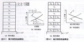
The winding structure on the left is very basic design.
The one on the right is better. Still very simple and traditional, but effective.
For a State of the Art design some extra effort is required.
Correct, the higher the number of layers does give an increase to the total capacitance, I'm not contesting that. Rather, I'm trying to see if you can elaborate on your "distribution of capacitance" comment. To put it more plainly, how is this more even distribution of capacitance accomplished?
Well, let's think again of the OPT winding like a capacitor.
Every capacitor have charge and discharge time. This means that at ANY audio cicle this virtual capacitor will have to charge AND discharge. The longer the time, the more it will affect the sound quality.
Now, we all now that if we have capacitors of similar structure but different value, the smaller cap will be faster than the bigger one.
We already told total stray capacitance is not so important, because is the result of a sum of several smaller capacitors.
Let's say we have a total stray capacitance of 300 picoF this could be made of a parallel of 4 smaller stray capacitances or maybe 12 smaller stray capacitances. Of course the second case will have a faster charge/discharge cicle. So the presence of the stray capacitance will affect less rising and decay time.
Now let's go back to the Hashimoto structure drawing posted by RajkoM.
In the case shown on the left we have 5 secondary sections interleaved with 4 primary sections. On the right we see that Hashimoto designer have chosen to split the primary sections in order to reduce the stray capacitances between primary and secondary winding. So we have 8 primary sections with smaller stray capacitances.
13 sections in total.
Of course this will help to get better rising and decay times and better sound.
We can imagine to bring the thing further and split also the secondary using a two slots former for the winding. Practically we repeat the first example winding two times, only width of each winding will be 1/2.
Sections count rises to 18.
We can go further and make this two juxtaposed windings like in the second example. Any half winding will have now 13 sections, for a total of 26.
Sound will improve further.
But winding time will be approx 4 times longer than our starting 9 sections winding.
I went even further and split any half winding in two. Practically a 4 or 8 slots winding, depending if you consider the primary or the secondary. Just try to imagine how long it takes to wind that and how difficult it is to work in those very narrow spaces (really difficult when you have to add layers of insulation material between the winding strata).
As I said this is not an OPT meant for serial production.
It is just meant to be the state of the art in OPT windings.
So far for what concerns stray capacitance between sections of primary and secondary winding. Extreme, but not new.
Another big problem is the even distribution of stray capacitances between strata. This has also been greatly improved adopting a technique that - to my knowledge - has never been used before in audio transformers.
Hope this explanation helped to understand a little better.
Last edited:
Ciro,
sorry for my break in conversation.
Hashimoto is splited secundary windnings, not primary.
If I read good Hashimotos right diagram, he stopped on total of 14 sections (4 primary and 10 secundary) because there is a best of (Lx x Cs) ratio.
BTW, I like your posts. They are so relaxing for one OPT manufacturer.
Best diying
Last edited:
A costum made core is easy to get, specially for a transformer company, even in small quantities it's easy.
costum anealing process looks nice in a advertising but dos it make sense?
You didn't say what the losses are and the thichness of the laminations.
You also didn't tell what the copperloss is of your transformer.
And a listing test .......which test?
costum anealing process looks nice in a advertising but dos it make sense?
You didn't say what the losses are and the thichness of the laminations.
You also didn't tell what the copperloss is of your transformer.
And a listing test .......which test?
Just confirming what I told. Measures (especially static measures) can only tell a part of the story. <snip>
Last edited:
There is a lot of information in Radiotron designers handbook about transformer technologie.
Telling about your ideas about transformer is interresting for those who like to make it them self. You spend a lot of time in your transformers but the results are not better then the other top transformers, telling that it sounds better is a very weak argument.
You can measure a lot more. Frequency respons secondair connected to earth and not connected to earth. 8 Ohm tap connected to a 4 Ohm or 16 Ohm restistor. Simulated speaker load, copperloss, coreloss, etc etc.
At this moment there is absolutly no argument that your transformeris superior to the best of Tango/Tamura transformers.
Well, let's think again of the OPT winding like a capacitor.<snip>
Ciro,
sorry for my break in conversation.
Hashimoto is splited secundary windnings, not primary.
If I read good Hashimotos right diagram, he stopped on total of 14 sections (4 primary and 10 secundary) because there is a best of (Lx x Cs) ratio.
BTW, I like your posts. They are so relaxing for one OPT manufacturer.
Best diying
Yes you are right, they split the secondary not the primary. Thanks for the correction.
Anyhow in practice very little changes, the effect on the distribution of stray capacitances is very similar. Also the increase in winding time (and production cost) is more or less the same.
Of course the further you take the splitting process, the best (at least within reasonable limits).
At least we agree on something.There is a lot of information in Radiotron designers handbook about transformer technologie.
Crowhurst articles (including the chapter on transformers in the radiotron designer handbook) are a very good starting point to learn about audio transformers.
When I'll be back to work I will give you infos about copperlosses.
But remember that copperlosses are linear losses, non linear losses matter much more.
You think so, I do not.Telling about your ideas about transformer is interresting for those who like to make it them self. .
If I buy in the future "very brand" OPTs, Ciro will be my first choice. Certainly !
Ok, there is interresting and interessting. 1 for people who understand what he wrotes and 1 for those who dosn't and think it means something for them too.
I don't know what the price is what he is asking but i can tell you this. Core materials and copper not more then €45,- and at most 4 hours to build a propper transformer ( incl coffee break 🙂 )
I don't know what the price is what he is asking but i can tell you this. Core materials and copper not more then €45,- and at most 4 hours to build a propper transformer ( incl coffee break 🙂 )
- Status
- Not open for further replies.
- Home
- Amplifiers
- Tubes / Valves
- Best SE output transformer for 300B - shootout