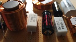
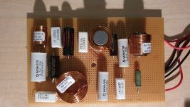
I accidentally discovered that music could couple from a XO connected to an amp to a XO connected to a speaker but not an amp. It was totally surprising to hear music playing from an unconnected speaker as I was connecting another XO to the amp.
I'd be more surprised if the thing started laying eggs.
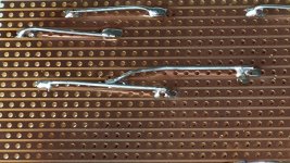
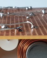
I and Chuck bought out another builder's stash of foils when he was getting out of the hobby, got them dirt cheap. These used here are 12AWG, and I just happened to have the right values to use them both. I use what I have if I can, and in tests preferred wire to foil on woofers, but these don't seem to suffer for it, nor did the tweeters in the tests before.Great info, Ben. That is a shiny XO. Do you like foil inductors nowadays?
Thanks for the compliments, fellas...
That’s handy but some inductors seem to have wire diameters larger than those holes. I think we used this board for prototyping circuits and there was a brand made by Vectorboards.
Very neat and professional looking. Nice!
Thank you @xrk !
Well, to be honest : it is also the easiest and most practical building method for me... Though the limit of this method appears in smaller type enclosures, where I do substitute plywood board for thinner PVC plates (see pics above), which takes less place, and so less volume to be removed from the useful volume of the enclosure.
T
When I originally posted this thread, I had already built my crossovers, and was ready to install them in the cabinet. It occurred to me that I might be doing things the hard way, so I asked the question. Thanks for all the feedback!

One thing I learned from this thread is the use of lever lock connectors. These have very low DCR, and can be used with any combination of solid core, stranded, 12 ga - 24 ga wire. Thankyou @xrk971
Another thing I learned (for next time) is that I can physically space the components much closer together. Thanks @wolf_teeth and others.
j.
What are these going in? Are you converting an existing active into a passive or is this a new build?
Hello I'm very sorry as I know this thread is somehow old, but I've wanted to post my recent crossover layout design for future reference.
Long story short, I was listening to a recent passive 2-Way speakers build of mine for about year and opted to downgrade my towers to use passive crossovers as well and saving space on power amps/channels, and while I've miss the time-delay ability the DSP still let me have a nice FR regardless on my small room.
The crossover was designed with REW+XSim+Listening and opted for an asymmetric 12dB/LF with an 18dB/HF for get decent phase and response etc. etc., well here is the crossover build for my "PRV 10MB800FT + HF10AK/LTH102" low tuned tower speakers with lots of insulation.
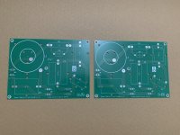
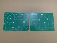
This are the crossovers PCB I've designed and ordered from JLCPCB, dual layer with large mirrored traces for high performance and reliability for portable/mobile/PA applications:

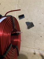
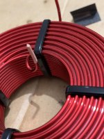
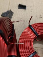
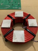
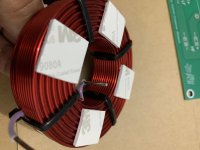
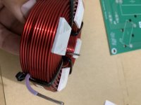
Hand-scrapping/shining the 14AWG inductors with 2 types of sand paper, one rough one fine before tinning the legs, and adding the thick foam pads:

Installing the 1/4"(6.3mm x 0.8mm) Faston connectors, made them a bit thigh to insert for easier installation soldering:
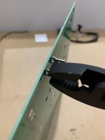
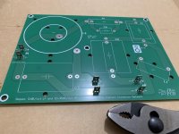
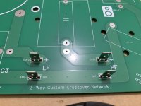
Soldering the heavier inductors with a moderately hot iron so the solder can get through and make a very strong contact on both layers traces:
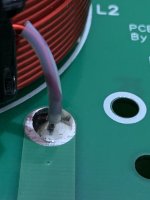
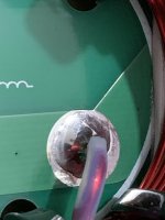
On smaller inductors and caps I use 3M VBH to hold the parts, I like it since strong bond and you can still easily swap parts without cleaning ugly glue/goop:
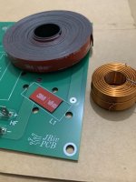
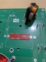
Crossovers almost ready with the PCB standoff and bottom view for reference:
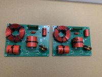
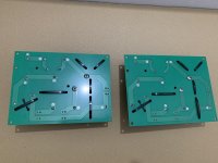

Notice the Teflon capillary tube on the inductors is not required at all, also the cable ties I use are the "Heat-Resistant" and/or automotive ones for reliability.
Best regards!
Long story short, I was listening to a recent passive 2-Way speakers build of mine for about year and opted to downgrade my towers to use passive crossovers as well and saving space on power amps/channels, and while I've miss the time-delay ability the DSP still let me have a nice FR regardless on my small room.
The crossover was designed with REW+XSim+Listening and opted for an asymmetric 12dB/LF with an 18dB/HF for get decent phase and response etc. etc., well here is the crossover build for my "PRV 10MB800FT + HF10AK/LTH102" low tuned tower speakers with lots of insulation.
This are the crossovers PCB I've designed and ordered from JLCPCB, dual layer with large mirrored traces for high performance and reliability for portable/mobile/PA applications:


Hand-scrapping/shining the 14AWG inductors with 2 types of sand paper, one rough one fine before tinning the legs, and adding the thick foam pads:


Installing the 1/4"(6.3mm x 0.8mm) Faston connectors, made them a bit thigh to insert for easier installation soldering:


Soldering the heavier inductors with a moderately hot iron so the solder can get through and make a very strong contact on both layers traces:


On smaller inductors and caps I use 3M VBH to hold the parts, I like it since strong bond and you can still easily swap parts without cleaning ugly glue/goop:


Crossovers almost ready with the PCB standoff and bottom view for reference:


Notice the Teflon capillary tube on the inductors is not required at all, also the cable ties I use are the "Heat-Resistant" and/or automotive ones for reliability.
Best regards!
Last edited:
This is my other high-power version featuring Q-Damping and larger size Air-Core or even I-Core inductors as the user need, also both crossovers version feature the "series" HF resistor attenuation which dissipates way less power compared to L-Pads, though this designs requires for very linear CD impedance such as HF108, HF10AK etc.
Here is the preview of the PCB's:
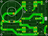

Best regards!
Here is the preview of the PCB's:


Best regards!
@xrk971 Thanks for the input, just wanted to design a passive XO with the lowest possible cross-talk/induction-coupling as possible hence there is no GND ground-plane in this ones unlike my previous ones, also being dual layer(with vias) it double the traces for increased power handling and reliability.
Though I will try and take some measurements soon on the cross-talk stuff compared with one of the ground-plane XO for comparison.
Some very old XO I've made over a ground-plane raw PCB for reference:
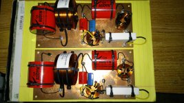
Best regards!
Though I will try and take some measurements soon on the cross-talk stuff compared with one of the ground-plane XO for comparison.
Some very old XO I've made over a ground-plane raw PCB for reference:

Best regards!
Nice work. I think a copper ground plane might change the value of the air core inductor slightly as it changes the permeability of the “air” core. Probably not enough to worry about.
Also, note that parallel air cores can and will talk to each other.
Here is an extreme example showing that it’s got enough power to drive a speaker through the air.
Also, note that parallel air cores can and will talk to each other.
Here is an extreme example showing that it’s got enough power to drive a speaker through the air.
Any magnetic part in XO is strictly no-no. Plz verify with a magnet all those small washers, nuts and connectors. If any of those are magnetic just solder instead.
http://www.troelsgravesen.dk/coils.htmHas anyone measured how close a coil has to be to the woofer magnet before it's behavior changes? I always worry about this in small speakers but never experimented with it.
- Home
- Loudspeakers
- Multi-Way
- Best practice for assembly/wiring of passive crossovers
