I would like to get the opinions of experienced builders on how they assemble and wire-up their passive crossover networks.
For instance, do you mount the components onto a board, or attach them directly to the cabinet wall? How do you attach the boards to the cabinet? Do you use mechanical disconnects in the wiring, or is everything soldered?
Do you run separate wires from the input terminals to the high-pass and low pass sections, or do you daisy chain the hot and ground wiring?
How do you test and validate your crossovers before installing them in the finished cabinet?
Thanks!
j.
Jim,
Few practices that I follow:
Look forward to learning about some good practices on this thread.
Few practices that I follow:
- Mount the components on a board, and try to place the board on inside of the base of the speaker if mounting internally.
- Nowadays try to have a "false base" that is external to the cabinet and place the XO board there.
- Use brass screws to fix the boards to the cabinet. Use 6mm ply as spacer/stand-off.
- I use XT30 and XT60 connectors for the wiring connections; example tweeters with XT30 and mid woofer connected with XT60, makes it easier to connect/disconnect and not make mistakes of connecting the wrong driver.
- Of course place the inductors with as much distance as possible between them, and place one another on different axis.
Look forward to learning about some good practices on this thread.
Last edited:

Hello Jim
I always lay them out on either small PCB or use thin sheet of painted plywood. I use 5 way binding posts for input and outputs to each driver and use banana plugs for quick connect disconnect. I typically keep them outside but have also mounted inside with an access panel.
I always do verification measurement for Frequency Response and verify Imp and Phase against the simulations. Always before permanent installation
Curious to see what everyone does.
Rob 🙂
Attachments

Last edited:
I am not sure if this is the “best” way but it’s how I do things and I find it very effective as it lets me progress from an initial simulation to a test in 30 minutes. I generally have complete “development” kit with almost all common passive component values for caps, inductors, and resistors on hand. I go from schematics to point to point using nothing but Wago spring clip connectors and some wire (if needed), listen and tweak the voicing, remeasure, tweak etc. this usually takes a week of listening to settle on the sound. But first sound generally comes 15min to 30min after schematic is generated from Xsim.
Here is what the Wago P2P looks like:

Then I make a more permanent P2P using a wooden board and zip ties and solder the leads directly and use wire jumpers if needed and this is what that looks like. I do this so that I can install stereo crossovers inside the cabinet:

Once I am happy with that I can continue to use it as is. If it’s a commercial project, I send the schematics to a crossover builder and they make me a PCB layout to inspect and then send me pre-production prototype XO’s with custom made components (if needed). For example, if I need 13.5uF MKP film cap, they will roll one in that exact value. Same with inductors etc. here is what the commercial one looks like:

I’ll test that and listen to it, measure it, tweak a resistor for final voicing (if needed) and then can make a determination to go to production.
My biggest recommendations to the speaker building enthusiast is to invest $200 in a nearly complete set of major passive crossover component values so that you have a development kit on hand. When making a speaker to keep, always buy new components for the BOM so that the development kit stays complete for the next project. Add more values as you go. I probably have $350 worth of stuff now as time goes by. But $200 to $250 is the best money I spent because I can listen to my new XO in 15min using Wago connectors. Here’s my XO dev kit:

Here is what the Wago P2P looks like:
Then I make a more permanent P2P using a wooden board and zip ties and solder the leads directly and use wire jumpers if needed and this is what that looks like. I do this so that I can install stereo crossovers inside the cabinet:
Once I am happy with that I can continue to use it as is. If it’s a commercial project, I send the schematics to a crossover builder and they make me a PCB layout to inspect and then send me pre-production prototype XO’s with custom made components (if needed). For example, if I need 13.5uF MKP film cap, they will roll one in that exact value. Same with inductors etc. here is what the commercial one looks like:
I’ll test that and listen to it, measure it, tweak a resistor for final voicing (if needed) and then can make a determination to go to production.
My biggest recommendations to the speaker building enthusiast is to invest $200 in a nearly complete set of major passive crossover component values so that you have a development kit on hand. When making a speaker to keep, always buy new components for the BOM so that the development kit stays complete for the next project. Add more values as you go. I probably have $350 worth of stuff now as time goes by. But $200 to $250 is the best money I spent because I can listen to my new XO in 15min using Wago connectors. Here’s my XO dev kit:
Last edited:
You can get the PCB made at any usual Chinese PCB maker like JLCPCB or PCBWay etc. You can ask many folks here on DIYA who are handy with layout to help or learn it yourself and use a free layout package like KiCAD.
I can’t share my PCB/XO maker but it’s single sided with small cuts and large traces.
I can’t share my PCB/XO maker but it’s single sided with small cuts and large traces.
Going forward I'm just going to 3D-print boards of my own design. First I'll lay everything out on paper and note dimensions. Then design in CAD and add things like places to attach zip-ties, screw holes, etc.
Then point-to-point solder. I do like those strips of wire loops that you can solder multiple wires to for things like common ground.
Then point-to-point solder. I do like those strips of wire loops that you can solder multiple wires to for things like common ground.
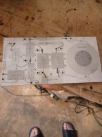
I use 1/8 hardboard with Molex SOLDER TERM .438 style 3 posts. Then I use zip ties and silicone caulk to secure the caps and coils to the board. I do spend a little time in QCAD laying out and print a drilling guide on card stock. Here are photos of the template and finished project. I do have experience with PCD design, but for me hand building two boards is fine, if I was making 10s or 100s then I would go with the PCBs. It is funny, I have spent the last month documenting every project I have done for the last few years. Here is a link to my web page that describes my design and build.
https://bellarossafabrica.net/loudspeakertech-p1
https://bellarossafabrica.net/loudspeakertech-p1
Attachments
I like xrk971 Wago connectors idea for initial set up/testing. The last x-over set I built was just a re-do of the factory values, so no testing was done.
My build thread here:-
https://www.diyaudio.com/community/...ronze-bx2-speakers-2010-2015-yr-model.388989/


Quotes from build:-
"In order to space the components further apart, away from the drivers for less interference, & to cover the hole left by the binding post panel, a suitably large flame proof ABS box made by Hammond was chosen to mount externally on the rear panel."
"I mounted all the components on a sheet of flame resistant, no holes/no clad, FR-4 PCB board, using the correct neutral cure clear silicone sealant & heat proof cable ties. I made certain in the design of the layout that I was able to join all the components directly to one another’s leads & soldered."
"For the main cable connections on the PCB, a M4 brass machine screw with a stainless steel serrated washer was placed through from the reverse side of the PCB board & a stainless steel serrated flanged nut was screwed down tight from the front side making a fixed “stud”. A plain stainless steel washer was placed over this, then the capacitor/resistor/inductor lead was wound once around the stud, then the cable M4 eye(s) were placed over, then another s/s serrated flanged nut is used to clamp everything together. This making maximum clamped surface area contact, as used in many other electrical situations!"
"When I remade the cables, I now used Molex OFC M4 tinned eyes without cable sheath grips at one end, & gold-plated push tabs at the other end. The wire ends were tinned & connectors were crimped as before. However, now I fed solder into the wire/crimp. All ends again have clear heat shrink sleeving over them. Again, the push tab ends were all carefully compressed to be a proper tight fit on the speaker tabs, due to “odd” sizing on the driver tabs."
My build thread here:-
https://www.diyaudio.com/community/...ronze-bx2-speakers-2010-2015-yr-model.388989/
Quotes from build:-
"In order to space the components further apart, away from the drivers for less interference, & to cover the hole left by the binding post panel, a suitably large flame proof ABS box made by Hammond was chosen to mount externally on the rear panel."
"I mounted all the components on a sheet of flame resistant, no holes/no clad, FR-4 PCB board, using the correct neutral cure clear silicone sealant & heat proof cable ties. I made certain in the design of the layout that I was able to join all the components directly to one another’s leads & soldered."
"For the main cable connections on the PCB, a M4 brass machine screw with a stainless steel serrated washer was placed through from the reverse side of the PCB board & a stainless steel serrated flanged nut was screwed down tight from the front side making a fixed “stud”. A plain stainless steel washer was placed over this, then the capacitor/resistor/inductor lead was wound once around the stud, then the cable M4 eye(s) were placed over, then another s/s serrated flanged nut is used to clamp everything together. This making maximum clamped surface area contact, as used in many other electrical situations!"
"When I remade the cables, I now used Molex OFC M4 tinned eyes without cable sheath grips at one end, & gold-plated push tabs at the other end. The wire ends were tinned & connectors were crimped as before. However, now I fed solder into the wire/crimp. All ends again have clear heat shrink sleeving over them. Again, the push tab ends were all carefully compressed to be a proper tight fit on the speaker tabs, due to “odd” sizing on the driver tabs."
Member
Joined 2003
Yes, 1/4" plywood.Components are attached usually just hot glue, ties for large inductors where glue may not hold well enough. For heat dissipating parts, E6000/goop adhesive. Don't get too carried away twisting wires together, I usually just bend a hook in the leads and solder, the soldered connection is reliable and the parts are easily disassembled without cutting the leads off if I decide to tweak things down the road. I don't care too much about making it look pretty, It's unseen once complete, and I don't instagram.do you mount the components onto a board, or attach them directly to the cabinet wall?
Board is screwed to the cabinet wall, try to fit in a space I can fit a stubby screwdriver. I use some craft foam between the board and wall and screw through it, the foam prevents vibrating/buzzing.How do you attach the boards to the cabinet?
Usually aim for some screw terminals on the crossover board so it can be disassembled and removed if needed, I've often used this product from Solen which works great for the task:Do you use mechanical disconnects in the wiring, or is everything soldered?
https://solen.ca/en/products/solen-322gds-dual-crossover-terminal-tinned-copper
Doesn't matter, whatever method makes the wiring easier and cleaner.Do you run separate wires from the input terminals to the high-pass and low pass sections, or do you daisy chain the hot and ground wiring?
Measure impedance, measure crossover transfer function, measure acoustic output, for each speaker individually.How do you test and validate your crossovers before installing them in the finished cabinet?
Last edited:
Several points to bear in mind:
A speaker cabinet is a high vibration environment (that's the whole point!), so every large component on a circuit board needs to be tacked down with glue or cable tied down to prevent movement and reduce the fatiguing of the solder connections.
Separate inductors should be mounted far apart and at right angles if possible to reduce flux-coupling between them - note there are 3 mutually perpendicular directions, X, Y and Z, so this is always possible with upto 3 inductors.
Make sure the crossover can take the maximum power the drivers can handle - drivers burn out relatively safely (as the coil is in a small gap) and are unlikely to start fires, but inductors on a crossover can potentially overheat and start a fire if undersized for the current. And exploding capacitors make a real mess... Mounting on FR4 is a good idea too (FR means fire retardent), well away from any internal wadding. Don't mount electronics on plywood!
Hot melt glue is not appropriate, it will simply melt when things get warm. I've seen it melt when left under a sunny window!
Member
Joined 2003
I wonder how ol’ Dan is doing? 😀
Seriously though, I’ve used that goop adhesive on boats, it will tear stuff apart before it comes loose so only use that if your sure it’s permanent!
Seriously though, I’ve used that goop adhesive on boats, it will tear stuff apart before it comes loose so only use that if your sure it’s permanent!
Even though I used to be fully active, I've made my speakers kind of a hybrid by using some crossover components internally.
The values were determined within Vituixcad, to make my arrays frequency shaded.
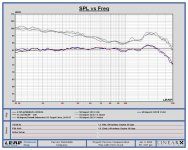
To be sure I matched the simulated values, I hooked up each filter to a known resistor value:

And compared that against a simulation of that same filter in XSim:

I did that for each filter that was used in my array and feel better knowing the filtering is working as expected.

A comparison of the filters as used in both arrays...
This way I was able to fine tune the filters to match what I came up with in Vituixcad.
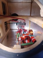
The boards I used to construct the filters on were inspired by what I had seen on Humble Homemade HiFi,
I figured I might as well make it look somewhat organized. I used either a rubbery glue or high temp double sided tape to mount the components on.
I used connectors to make it all serviceable as I had done that with rest of the array construction too. (plus that made it easy to remove the filters if I didn't like the results for some reason 😀, luckily that didn't happen). Coils as far apart as I could get them and oriented to match what Troels showed us as good options.
Obviously it worked out quite well as I could get the sims and the real crossover boards (and both arrays) to match.
I'm still actively filtering the arrays using DSP FIR filters and whatnot. So it's a real hybrid construction. These frequency dependent filters make sure the vertical directivity improves compared to an unfiltered array (and gets rid of comb filter dips/peaks).
The values were determined within Vituixcad, to make my arrays frequency shaded.
To be sure I matched the simulated values, I hooked up each filter to a known resistor value:
And compared that against a simulation of that same filter in XSim:
I did that for each filter that was used in my array and feel better knowing the filtering is working as expected.
A comparison of the filters as used in both arrays...
This way I was able to fine tune the filters to match what I came up with in Vituixcad.
The boards I used to construct the filters on were inspired by what I had seen on Humble Homemade HiFi,
I figured I might as well make it look somewhat organized. I used either a rubbery glue or high temp double sided tape to mount the components on.
I used connectors to make it all serviceable as I had done that with rest of the array construction too. (plus that made it easy to remove the filters if I didn't like the results for some reason 😀, luckily that didn't happen). Coils as far apart as I could get them and oriented to match what Troels showed us as good options.
Obviously it worked out quite well as I could get the sims and the real crossover boards (and both arrays) to match.
I'm still actively filtering the arrays using DSP FIR filters and whatnot. So it's a real hybrid construction. These frequency dependent filters make sure the vertical directivity improves compared to an unfiltered array (and gets rid of comb filter dips/peaks).
Has anyone measured how close a coil has to be to the woofer magnet before it's behavior changes? I always worry about this in small speakers but never experimented with it.
Inductive coupling is much easier between laminate cores. I've placed them close to magnets and nullified or drastically reduced their value due to the field transferred to the core. Air cores are pretty much oblivious to magnets. There is a thread on MAC with tests shown by ugly_woofer.
As to my approach, I use pegboard, zip ties, and occasionally E6000 glue. The E6000 can be cut with a knife if something needs changed, but with considerable effort. I do not use hot glue.
Pegboard both gives you tie-down points and mounting holes, so this is advantageous. Unless you are doing prosound or running thousands of watts, this medium is fine. Sonus Fabre still uses this method, as do many other hifi companies. I have not had one fail. If I want more strength in the board, i can coat the porous side with glue or glue 2 pieces together back to back. Xovers can get heavy. If you are using a heavy component, do not just use one tie. Use multiple ties, and invest in a zip-tie gun from Paladin or Panduit. During shipping or transport, i have seen slacked or single ties break many times. 8# ties are great for larger components, smaller are good for resistors. If you want the best ties, or wind your own coils, use the Thomas and Betts Tyrap brand with the steel barbed round head. Otherwise T&B standard or any other are fine.
During prototyping, I have been known to use the wago clips, alligator jumpers (make sure they have continuity or make your own), or clip leads with a single alligator. This is the initial stage, just like XRK posted. You have to put together a trial run and see if it survives the listening and verifying the previous simulation with measurements. Double check your wiring 3 times before hooking up. In this stage, it is also beneficial to have a biamp terminal on the cabinet. If it is a 3way, you can run the woofer wires out the ports, and connect the mid and tweeter internally to the posts. Using an alligator jumper or a wired SPDT switch can allow padding changes from 2 different components in either the experimental stage or after the assembly for verification. I know Jim likes 2 different sets of padding for 2 different music styles. Including an exterior mounted switch in the terminal cup can allow this function.
Layout is something I have alot of fun with. I try to make the circuit exist without jumpers if at all possible on the boards. Keep coils at right angles, and I try to keep resistors along the edges for ventilation in case they get a little warm.
Wiring to and from the board....
If you use the dual binding post setup on the cabinets, you can separate the inputs and use the exterior jumpers for connection. I have done this, or hardwired all to one pair of leads and then to the one set of posts. If you still use the external jumpers no one will know one set is not connected. I have seen people use different resistors as the exterior jumpers to change padding from one pair on the woofer to the other pair for the tweeter. For connection to the board, use nonferrous barrier strips if you go that route. Euro style strips are common here. This is because the iron in close proximity to coils can increase their value. Lots of aluminum adjacent to coils can reduce their value like a shorting ring, so be careful here as well. This is why someone above mentioned brass mounting screws for both the board and components. If not using strips, this saves you more space on the board, but sometimes they can be a necessity. Glue or screws to mount them is commonplace. If you just solder leads from the boards, zipping the wires to a spot on the board supplies a secure connection and strain relief to prevent pulling on components. Quite a few builders like to use 0.25" male leads for connections on the boards. You can get these in screw on style, or just glue or epoxy them to the boards for connections.
Some people prefer to keep networks for the individual drivers separate, and wire them individually.
Jim, you've seen my 3d construction on the Bottleships, and normally it doesn't require that much complexity for fitment. However, a smaller daughter pegboard for small components has been beneficial in the past where space is of concern. Curt Campbell did a writeup called Nodal Analysis that helps newer passive builders break down a circuit and how it can be applied into physical form. Once you have that laid out, be aware you can go vertical and not have to think of a xover in only a single plane.
Wooden or 3d printed cradles have been used by some with or as boards to make mounting cylindrical components on their sides easier too.
Invest in a round nosed set of jewelry needle nose pliers for curling leads to solder. Eyelets are easier than twisting, and snipping them in case of change removes less length while salvaging the component for a future use. Heat the joint and not the solder, and the solder will flow to the heat.
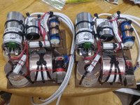
Here is a recent example from me. I used a small daughter board for the smaller components and resistors, as well as a place for securing soldered leads. I made cradles to mount the large ASC cap atop the laminate core beneath. It is 6x7 and about 4.25 high, and about 5 pounds.
Please ask if you have any questions,
As to my approach, I use pegboard, zip ties, and occasionally E6000 glue. The E6000 can be cut with a knife if something needs changed, but with considerable effort. I do not use hot glue.
Pegboard both gives you tie-down points and mounting holes, so this is advantageous. Unless you are doing prosound or running thousands of watts, this medium is fine. Sonus Fabre still uses this method, as do many other hifi companies. I have not had one fail. If I want more strength in the board, i can coat the porous side with glue or glue 2 pieces together back to back. Xovers can get heavy. If you are using a heavy component, do not just use one tie. Use multiple ties, and invest in a zip-tie gun from Paladin or Panduit. During shipping or transport, i have seen slacked or single ties break many times. 8# ties are great for larger components, smaller are good for resistors. If you want the best ties, or wind your own coils, use the Thomas and Betts Tyrap brand with the steel barbed round head. Otherwise T&B standard or any other are fine.
During prototyping, I have been known to use the wago clips, alligator jumpers (make sure they have continuity or make your own), or clip leads with a single alligator. This is the initial stage, just like XRK posted. You have to put together a trial run and see if it survives the listening and verifying the previous simulation with measurements. Double check your wiring 3 times before hooking up. In this stage, it is also beneficial to have a biamp terminal on the cabinet. If it is a 3way, you can run the woofer wires out the ports, and connect the mid and tweeter internally to the posts. Using an alligator jumper or a wired SPDT switch can allow padding changes from 2 different components in either the experimental stage or after the assembly for verification. I know Jim likes 2 different sets of padding for 2 different music styles. Including an exterior mounted switch in the terminal cup can allow this function.
Layout is something I have alot of fun with. I try to make the circuit exist without jumpers if at all possible on the boards. Keep coils at right angles, and I try to keep resistors along the edges for ventilation in case they get a little warm.
Wiring to and from the board....
If you use the dual binding post setup on the cabinets, you can separate the inputs and use the exterior jumpers for connection. I have done this, or hardwired all to one pair of leads and then to the one set of posts. If you still use the external jumpers no one will know one set is not connected. I have seen people use different resistors as the exterior jumpers to change padding from one pair on the woofer to the other pair for the tweeter. For connection to the board, use nonferrous barrier strips if you go that route. Euro style strips are common here. This is because the iron in close proximity to coils can increase their value. Lots of aluminum adjacent to coils can reduce their value like a shorting ring, so be careful here as well. This is why someone above mentioned brass mounting screws for both the board and components. If not using strips, this saves you more space on the board, but sometimes they can be a necessity. Glue or screws to mount them is commonplace. If you just solder leads from the boards, zipping the wires to a spot on the board supplies a secure connection and strain relief to prevent pulling on components. Quite a few builders like to use 0.25" male leads for connections on the boards. You can get these in screw on style, or just glue or epoxy them to the boards for connections.
Some people prefer to keep networks for the individual drivers separate, and wire them individually.
Jim, you've seen my 3d construction on the Bottleships, and normally it doesn't require that much complexity for fitment. However, a smaller daughter pegboard for small components has been beneficial in the past where space is of concern. Curt Campbell did a writeup called Nodal Analysis that helps newer passive builders break down a circuit and how it can be applied into physical form. Once you have that laid out, be aware you can go vertical and not have to think of a xover in only a single plane.
Wooden or 3d printed cradles have been used by some with or as boards to make mounting cylindrical components on their sides easier too.
Invest in a round nosed set of jewelry needle nose pliers for curling leads to solder. Eyelets are easier than twisting, and snipping them in case of change removes less length while salvaging the component for a future use. Heat the joint and not the solder, and the solder will flow to the heat.
Here is a recent example from me. I used a small daughter board for the smaller components and resistors, as well as a place for securing soldered leads. I made cradles to mount the large ASC cap atop the laminate core beneath. It is 6x7 and about 4.25 high, and about 5 pounds.
Please ask if you have any questions,
Attachments
- Home
- Loudspeakers
- Multi-Way
- Best practice for assembly/wiring of passive crossovers