Thank you for the clarification. You mentioned you had the EPs and they just seemed like the obvious choice from a quality and performance standpoint. It could be a fairly straightforward matter to switch in different low pass caps for the different applications should you choose.
Thanks for your contribution to this thread! When I pass the signal through an active crossover, the amp gets just what it is supposed to amplify. When I use a passive crossover, I send the whole signal to each amp, but the amplifier is unable to pass any current to the speaker through the OPT for the portions of the signal that are rolled off by the crossover. This is how it was explained to me in another thread when I asked if I should insert a line level crossover between my source and each amplifier when the amps were driving their portion of the signal through a passive crossover.
Another option, that I first saw in notes from Paul Klipsch dated 1945, is to build a single amplifier with two output transformers, each dedicated to its frequency range, with a higher impedance (5 KOhms in his case) crossover between the output valves (push-pull 6B4's in his case) and the output transformers. Fairly straight forward to do, even back before DTN Williamson and modern output transformer designs - folks commonly wound their own inductors during the War period.
YOS,
Chris
YOS,
Chris
Chris: That’s very interesting. A crossover between the tube final and two output transformers, one for HF and one for LF.
Do you know at what wattage these measurements were taken?
its not only the wattage, its also the source impedance that is important to know, without that info, those graphs are meaningless
The principle of output level crossover, as opposed to speaker level one, has several advantages. The most important is the small size of crossover capacitor, so that highest quality capacitor can be used without considerable expense. Another advantage is simple design of output transformers. The main transformer can be optimized for mid frequencies; it may have high primary inductance to virtually eliminate saturation distortion, without concern for high frequency performance. It does not need interleaving; on contrary, it should be purposly designed to have certain leakage inductance, which will serve as crossover' s L element. HF transformer can be wound on very small highest permeability gapless core (supermalloy or nanocrystalline), also without interleaving. Due to winding proximity, frequency response will extend well beyond the audible range. As a bonus, winding your own, you can have highest quality transformers without outlay of thousands of dollars on exotic stuff.
sser2: do you have a link for how to design an output level crossover? I had a look but couldn’t find anything.
No links, I did my own calculations. Here is an example.
In Rauland 2A3 parallel push-pull amplifier, the output load is 1.5 K. Original output transformer is not interleaved, it has primary inductance of 45 H and leakage inductance of 9 mH. For the crossover point of 1 kHz, total series inductance should be 25 mH (from the formula z=2piFL, so 16 mH inductor should be added (in this case split inductor because there are 2 secondary halves). High frequency transformer is wound on 30 mm Vitroperm 500 toroid core, it's primary is 2 H. HF transformer is connected across plates in series with 0.1 uF capacitor (1.5 k impedance at 1 kHz). Basically, capacitance and series inductance (the sum of leakage inductance and additional series inductor) should have impedance at the crossover frequency equal to stage's load impedance - for second order attenuation with -3dB at crossover point.
In Rauland 2A3 parallel push-pull amplifier, the output load is 1.5 K. Original output transformer is not interleaved, it has primary inductance of 45 H and leakage inductance of 9 mH. For the crossover point of 1 kHz, total series inductance should be 25 mH (from the formula z=2piFL, so 16 mH inductor should be added (in this case split inductor because there are 2 secondary halves). High frequency transformer is wound on 30 mm Vitroperm 500 toroid core, it's primary is 2 H. HF transformer is connected across plates in series with 0.1 uF capacitor (1.5 k impedance at 1 kHz). Basically, capacitance and series inductance (the sum of leakage inductance and additional series inductor) should have impedance at the crossover frequency equal to stage's load impedance - for second order attenuation with -3dB at crossover point.
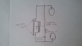
Thanks for the example. Is the connection from the plate of the power tube split into two, with one side getting the inductor, and the other side the capacitor, and then to the two separate output transformers? A schematic would be very help[ful.
Sorry for the ugly sketch. Transformer secondaries are not shown.
Attachments
Last edited:
Sorry for the ugly sketch. Transformer secondaries are not shown.
It’s not ugly, and very helpful. Thanks!
For L = 25 mH @1kHz
z = 2 * pi * 1^3 * 25 * 10^-3 = 157 ohm
Sorry, my error. It should be 250 mH.
PWK envisioned it as a 2 pole Butterworth, with LC network before the low frequency OPT (which would have the same iron core as a conventional one) and a CL network before the high frequency transformer (which would be smaller and optimized for its use, but not center-tapped). Neither transformer would contribute to the crossing over. (Crossovery?)
His original version used a bifilar choke in the LC and 2 equal capacitors of twice calculated value each in the CL. Not sure that's necessary, but is technically "correct".
YOS,
Chris
His original version used a bifilar choke in the LC and 2 equal capacitors of twice calculated value each in the CL. Not sure that's necessary, but is technically "correct".
YOS,
Chris
I believe high order crossovers introduce more problems than they solve. Low order XO requires broadband capability of both mid and high frequency drivers. Such drivers do exist.
PWK actually used single pole electrical networks for his commercial speakers up into the early 1970's, when he was convinced?/forced? to change the tweeter high pass to 3 pole (and add a parallel Zener) due to the exuberance of the times.
S. Linkwitz made a point that there cannot be less than a 2 pole high pass acoustically because all drivers have a massxcompliance resonance (a second order function), but that's a whole different kettle of critter.
All good fortune,
Chris
S. Linkwitz made a point that there cannot be less than a 2 pole high pass acoustically because all drivers have a massxcompliance resonance (a second order function), but that's a whole different kettle of critter.
All good fortune,
Chris
- Home
- Amplifiers
- Tubes / Valves
- Best OPT for use over 400 HZ