Hallo Sonny,
you are right. Nevertheless in most cases the sonic quality by only resistor instead of a OP-AMP based I/U converter is better (only by DAC ICs with R2R at output) I haven't try AD797 together with external differential jFET input amp (this could be better solution as only resistor) but compared to the OP-Amp types OP275, OPA2604, 2132 and 627 only resistor is the better solution (it is my experience) Additional enhancing of sound quality I get, when I replace the resistor through a common base circuit (common gate circuit) with current source and output buffer like D1 from Passlabs. Who knows about checking a discrete I/U circuit by p-spice simulation?
Best regards
Andreas
OpAmps.....
You know .. The AD797 is one of the best audio opamp designs around. The second stage, The VAS stage is very very very high impedan't. Followed by a high quality buffer. It's impressive performance is due to a very high. It's noise figure of 0.9nV is equalent to 50Ohm resistor. It is not a jfet input. So as soon the feedback resistors rise in value. The current noise will be dominant. In the datasheet an example with feedback resistor in size of 1K will result in 3nV. At this point a cmos or jfet opamp has a better performance.
To use opamp's in I/V conversion the openloop gain must be as high as possible to get as linear conversion as possible. The lowpass filter should be added to the feedback loop of the I/V converter to get optimum performance. The reason is the glitches that is present in some DAC's ...
The Bandwith of the opamp's should be at least 10 times higher than the selected crossover frequence. So if you select a lowpass filter of 100KHz The GPBW of the opamps should be at least 100KHz * bandwitdthheadroom * gain_of_opamp. So if you have a gain of 10 times and a LP frequ. of 100KHz .. Then the opamp should have at least 10MHz. With a GPBW of 10MHz and a freq. of 100KHz you will only have a openloop gain of 100 times ~the opamp will not be very linear....
If you want's to have a openloop gain of 10.000@20KHz (The opamp will be very linear) then the GPBW should be atleast 200MHz.
Something to think about. 😎
Hallo Sonnya, best thanks for all informations. How I can actually tested an I / V converter circuit by pSpice simulation? - I have the CAD software "Circuit Maker". The main problem, that I see is how I prepare the generator with an internal resistance of 0 ohms for I-Output? - at best I open in this context a new topic
"what must I do to simulate I/U (I/V) converters for TI PCM DAC. with R2R (e.g. PCM1704)?"
"what must I do to simulate I/U (I/V) converters for TI PCM DAC. with R2R (e.g. PCM1704)?"
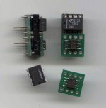
two different monolithic opamps on adapter
Nice to see this very old thread living again from time to time...
I have tried searching but ended up with nothing.
In advance I apologize for my ignorance, and if my idea is some kind of engineering blasphemy or so... because I can not believe that no one came up with same idea before...
 So I'm suspicious why nobody came up with combining two two different monolithic opamps on adapter in places dual opamps are used.
I beleive it was very common in many diyers favorite - TDA1541 based players, to use dual opamps for conversion and output stage.
I thought why not use AD844 in place of first opamp for I/V conversion and my favorite AD797 as second?
My friend has tried many combinations in his marantz 94 because in it's circuitry it's is already two mon.opamps per channel.
Nice to see this very old thread living again from time to time...
I have tried searching but ended up with nothing.
In advance I apologize for my ignorance, and if my idea is some kind of engineering blasphemy or so...
because I can not believe that no one came up with same idea before... So I'm suspicious why nobody came up with combining two two different monolithic opamps on adapter in places dual opamps are used.I beleive it was very common in many diyers favorite - TDA1541 based players, to use dual opamps for conversion and output stage.
I thought why not use AD844 in place of first opamp for I/V conversion and my favorite AD797 as second?
My friend has tried many combinations in his marantz 94 because in it's circuitry it's is already two mon.opamps per channel.
Your idea is not uncommon, at least not for me or in the CD63/67 mods thread 😀
I've been experimenting with lots of opamps over the last few years. My favorite combo is the AD8610 with AD8510 for my CD67-OSE at the moment. For a TDA1541 DAC, the AD797 is a nice one indeed, but I also like OPA211 and AD8597.
Regards,
Ray
I've been experimenting with lots of opamps over the last few years. My favorite combo is the AD8610 with AD8510 for my CD67-OSE at the moment. For a TDA1541 DAC, the AD797 is a nice one indeed, but I also like OPA211 and AD8597.
Regards,
Ray
Attachments
In non standard design and proper PCB tracing and PSU - NE5534P(TI), LME49710, LT1468Best opamp for I/V conversion?
In standart the best would be AD846
Its not true, input BJT stage without an emittern resistors has very bad linearity (and distortion of input stage is not suppressed by negative feedback!), RF interference can easily overload the input of that opampThe AD797 is one of the best audio opamp designs around.
for best performance input diff voltage should be very low (several millivolts).
Output stage also has noy good linearity...
To obtain maximum results using this opamp should be very accurate, with an excellent understanding of the theory of negative feedback and characteristics of different opamp
that will not help from glitchesThe reason is the glitches that is present in some DAC's
its very poor linearyty opamp, good opamp should have GBWP (in 0-100kHz) 40-100MhzWith a GPBW of 10MHz
Last edited:
NE5534 also has no local feedback in the input stage. UGB is only 10MHz. Distortion sucks.
I don't like the 5534.
Ray
I don't like the 5534.
Ray
Last edited:
yes, his input BJT stage without an emittern resistors, GPBW 60Mhz(UGB is not informative, 5534 has 2pole compensation), output stage has great linearity even without NFNE5534 also has no local feedback in the input stage. UGB is only 10MHz. Distortion sucks.
I don't like the 5534.
With proper schematic, PSU and PCB tracing, by linearity he has only few competitors with high voltage PS (LME49710, LT1468, ADA4898).
for tweaking this opamp for 99.9% DIYers is unsuitableTo obtain maximum results using this opamp should be very accurate, with an excellent understanding of the theory of negative feedback and characteristics of different opamp
Last edited:
UGB and GBW are very similar, so I don't know where you get the 60MHz from.
And how does it do with a few 100 pF of capacitive load? Is it still linear then?
Regards,
Ray
And how does it do with a few 100 pF of capacitive load? Is it still linear then?
Regards,
Ray
GBW = gain 57-60db f=100kHz
If you compensate pole all right
As I talk above its not a simple opamp in using, only professionals can use 5534 correctly (SSL, Amber etc)
If you compensate pole all right
As I talk above its not a simple opamp in using, only professionals can use 5534 correctly (SSL, Amber etc)
That is the uncompensated GBW. The more you compensate, the smaller GBW will be. GBW can therefore not be 60MHz compensated.
It will be about 10MHz with 22pF compensation and 100pF load. See datasheet.
100pF is not an unpractical value if you load the opamp with a filter stage or interconnect at the output.
Regards,
Ray
It will be about 10MHz with 22pF compensation and 100pF load. See datasheet.
100pF is not an unpractical value if you load the opamp with a filter stage or interconnect at the output.
Regards,
Ray
ofcoarse, with miller compensation, but why to do that 🙂 the best compensation that do not give disadvantages is RC input compensation.That is the uncompensated GBW. The more you compensate, the smaller GBW will be. GBW can therefore not be 60MHz compensated.
5534 from TI is de fakto unity gain stable (TI has another layout), 5534 from others(NJM,TDA,SSM) will oscillate with unity gain&small output capacitor
it is IDIOTIC schematic simply for exampleIt will be about 10MHz with 22pF compensation and 100pF load. See datasheet.
for ANY opamp any capacity at the output(&input) must be isolated (it is not difficult) or properly compensated100pF is not an unpractical value if you load the opamp with a filter stage or interconnect at the output.
my regards,
Nazar
RC input compensation still reduces the effective practical bandwidth that we can use, that's the point of compensation, right?
Ray
Ray
Your idea is not uncommon, at least not for me or in the CD63/67 mods thread 😀
I've been experimenting with lots of opamps over the last few years. My favorite combo is the AD8610 with AD8510 for my CD67-OSE at the moment. For a TDA1541 DAC, the AD797 is a nice one indeed, but I also like OPA211 and AD8597.
Regards,
Ray
To get back on topic🙂! If we are chasing high slew rate for I/V opamp AD844 with its 2000 V/μs seems to be one of the best here or I'm missing something?
Last edited:
To get back on topic🙂! If we are chasing high slew rate for I/V opamp AD844 with its 2000 V/μs seems to be one of the best here or I'm missing something?
that there's no obvious reason to chase high V slew rate?
except as a proxy for increased linear input range - but why not 1st design the circuit for low input V error?
DAC I/V for reproducing audio doesn't need to move the output faster than the filtered audio frequency output signal's rate
there's no need to reproduce the step/switching glitches - they should be flitered out as early as possible
high current/low open loop Z output stage would be a better way of soaking up the glitches thru the feedback C
there's no need to reproduce the step/switching glitches - they should be flitered out as early as possible
That's right, they should be filtered by, well... a filter, but not limited by the opamp's slew. That will most likely create intermodulation distortion.
Ray
We cant filter glitch, but we don’t have to do that, we only can reduce slew rate of glitch impulse (energy would be the same but with low-frequency spectrum) so they do not overload opamp input stage, then we can use highly linear low frequency opamp (4898, 1468, 49710 etc).there's no need to reproduce the step/switching glitches - they should be flitered out as early as possible
high current/low open loop Z output stage would be a better way of soaking up the glitches thru the feedback C
Use of video opamp in I/U is fight with the consequence rather than cause
regards,
Nazar
Are there new experiences?
In the meantime was launched various new OP-AMP IC's from TI/Burr Brown, Analog Devices and National Semiconductor.
In the meantime was launched various new OP-AMP IC's from TI/Burr Brown, Analog Devices and National Semiconductor.
- Home
- Source & Line
- Digital Line Level
- Best opamp for I/V conversion? (DAC)