I am the poster of that link.
See this link: http://i48.tinypic.com/34s14cp.jpg
See the RED arrow - its all self-explanatory
See this link: http://i48.tinypic.com/34s14cp.jpg
See the RED arrow - its all self-explanatory
Any chance of posting further instructions. I see the reg. but can't figure out where the leads go. My board has a small yellow cap close-to that position.
I'm a bit new to all this.
I'm a bit new to all this.
(1) Remove the yellow plastic cap.
(2) Drill 1 hole for the 3-leg Reg to go in.
(3) Now you have to cut the copper trace of that offending +12V which was going into Pin-22 of CS-8412.
(4) Short the links.
http://i46.tinypic.com/hvvyo5.jpg
(2) Drill 1 hole for the 3-leg Reg to go in.
(3) Now you have to cut the copper trace of that offending +12V which was going into Pin-22 of CS-8412.
(4) Short the links.
http://i46.tinypic.com/hvvyo5.jpg
If you have already replaced the Analog power Regs to 7812 and 7912 on the DITB from 7805/7905, then here's the way to proceed.
(1) Power up the DITB. Take your multimeter set to Volts DC and then with the probes, touch PIN-22 +V(analog) using RED & PIN-21 Gnd(analog)using BLACK probes of your multimeter to CS-8412. Measure the incoming voltage. It would be around +12 volts or so.
(2) Trace back the copper track from PIN-22 of CS-8412 backwards. Somewhere in between that trace, you will need to CUT THE TRACK OFF so that there's no voltage flow.
(3) Remove/desolder Yellow cap C14. Of the 2 pins there, one is connected to PIN-22 while the other to Gnd.
(4) Take a 7805 reg, with Pin-1 IN, Pin-2 Gnd, Pin-3 OUT. Mount the Pin-3 OUT of the Reg to the thru-hole of that C14 that in-turn connects to Pin-22 of CS-8412.
(5) Pin-2 of Reg goes to the remaining other thru-hole of C14 that connects to Gnd.
(6) Pin-1 of Reg will go into a NEW HOLE that you'll need to drill on the DITB PCB.
(7) Now take a single insulated wire and solder to Pin-1 (IN) of the Reg. The other side goes to the copper track where you cut the trace & the originating solder point of that offending +12V voltage.
(8) Using the multimeter, with Black probe to Gnd, measure voltage on IN and OUT. IN = +12V, OUT = +5V.
If you achieve this - you are done !! That CS-8412 is now saved & will survive.
Report back:
I replaced the regulators with 12 volt versions. Did a quick power up to see if everything was OK. Oddly, the 5 volt digital supplys were reading zero, and the 12 volt supply was over 16 volt!
I then quickly installed the additional 5 volt regulator at the CS8412 before any futher testing
Turns out that when I drilled-out the PCB to suit the larger T0-220 regs, I must have removed the through-plating. Once I soldered the regs on top of the PCB, everything measured OK.
But, when I plugged it into to the system to check the sound - the lock LED failed to light, and there was no sound.
I hope I have fried something. Any ideas?
Nothing to panic ...
First of all - power up the DITB and look around to see WHY you are not getting the +/- 5 volts Digital ?
Without this supply, the PCB won't function and LOCK will not work.
Then - once this is sorted, and if problems remain, we will deal with it.
First of all - power up the DITB and look around to see WHY you are not getting the +/- 5 volts Digital ?
Without this supply, the PCB won't function and LOCK will not work.
Then - once this is sorted, and if problems remain, we will deal with it.
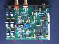
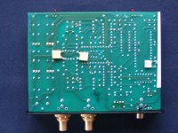
Here are my photos.
White PVC tape on the edge to prevent the cut and scraped track from making contact with the case.
I had to replace the output sockets, as one was damaged.
Components used:
470uF 25v Panasonic FC after 12volt regulators
47uF 50v Hitano low ESR as opamp bypass - .47uF film in parallel
5v +ve regulator (TO-92) on pin 22 of CS8412
I just used what I had on the bench. If I get the box to work again, I may upgrade the parts.
Attachments
all looks good on the pics.
Just check to see +5V is going into the CS8412 ? while +12V is what should be the TO92 reg receiving it and dropping it to +5
Also, check to see if any other trace/s got cut ? Remember this is a double-sided PCB so you need to hold the PCB over strong light and inspect
Otherwise, there's no reason why the LOCK is playing up
My concern is that the initial (faulty) 16+ volts to pin 22 of the CS8412 may have damaged it.
I'll do a thourough inspection later.
I'll do a thourough inspection later.
I have found something. The extra hole that I drilled for the TO-92 reg, passed through the ground plane on the top of the PCB.
I will drill a new hole later today. Although, I find it improbable that I would get any voltage readings had the regulator lead been shorting the 12 VA to ground.
Hopeful that this will result in a DAC that operates.
I will drill a new hole later today. Although, I find it improbable that I would get any voltage readings had the regulator lead been shorting the 12 VA to ground.
Hopeful that this will result in a DAC that operates.
It seems VERY likely to me that you will need to replace the CS8412. Fortunately, these have become much easier to get on ebay & elsewhere than they were a few years ago. If you do not have a vacuum desoldering station(Hakko 707, 808, Weller DS-701, DS2000, etc.), the only safe way to desolder it is to take a very fine pair of wire cutters & clip each pin at the body of the chip, removing the chip. Then, melt each pin out individually, without trying to remove solder. At this point, you can then desolder each hole, using ChemWik desoldering braid or a skillfully used solder sucker.
The OPA2134 may be the best although sound is subjective
with hi Z inputs it is better then the LM4562
both beat the OP275
at gains below 5 the older LF353 gives the OPA2134 good competition
* TL072 and LF353 are Not equal
with hi Z inputs it is better then the LM4562
both beat the OP275
at gains below 5 the older LF353 gives the OPA2134 good competition
* TL072 and LF353 are Not equal
I've just ordered a CS8412 - just in case.
Thank you for all the help so far - sorry for taking your thread off on a tangent.
Once, hopefully, my DITB is working, I'll be able contribute something meaningful on the opamp topic.
Thank you for all the help so far - sorry for taking your thread off on a tangent.
Once, hopefully, my DITB is working, I'll be able contribute something meaningful on the opamp topic.
CS8412 replaced and it works again. I tried the optical input - no lock or sound. As I never tried the optical in before the mod, I have no way of know if this was a previous fault.
Anyway, it's sounding good.
Anyway, it's sounding good.
Anyway, it's sounding good.
Am glad to see it is working - after a long struggle .. 🙂
- Status
- Not open for further replies.
- Home
- Source & Line
- Digital Source
- Best OpAmp for Audio Alchemy DITB