I am searching for PNP replacement transistors for an audio mixing console. The stock ones (PN4355) are rather noisy. The QUIETEST transistor I have found so far is the ZTX951; but I am not sure it will also provide the least distortion. The power supply rails are +/- 18 volts. The typical microphone used would be a Shure SM-57-- ~310Ω source impedance at 1.6 mV level; so I'll need ~55 db of gain to get to line level, which will feed an OPA 1642 opamp.
Suggestions?
Suggestions?
Last edited:
All bipolar transistors distort about the same when driven from a low impedance and not biased in high injection. The relatively large capacitances might be an issue if there is a feedback loop around the transistor.
The feller in this thread found otherwise when substituting a ZTX:All bipolar transistors distort about the same when driven from a low impedance and not biased in high injection.
Interesting Soundcraft 1600 mod results
He reported a 1 to 6 db increase in distortion. It may very well be that the ZTX951's performance is a trade-off between noise and distortion.
Perhaps cascoding the ZTX951 would help, by removing voltage swing from its collector? It would mean modding the circuit.
The feller in this thread found otherwise when substituting a ZTX:
Interesting Soundcraft 1600 mod results
He reported a 1 to 6 db increase in distortion. It may very well be that the ZTX951's performance is a trade-off between noise and distortion.
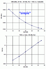
I haven't a clue what his graphs mean, +20 dB distortion seems rather a lot to me, but it could be that the whole thing is oscillating due to the big capacitances of the ZTX devices.
When I was testing my balanced mic preamp modules I noticed a very marginal improvement (maybe 1 or 2 dB) in the noise floor when I changed out the BC560Cs for 2N4403s. Distortion didn't really change much if at all.
Circuit shown in:Best transistor in what microphone preamp topology ?
Interesting Soundcraft 1600 mod results
post #20
Hmmmm.....well, that's interesting....a 1 to 2 db improvement in each of eight channels could be significant, methinks. It sure is tough to find useful noise specs of transistors.....When I was testing my balanced mic preamp modules I noticed a very marginal improvement (maybe 1 or 2 dB) in the noise floor when I changed out the BC560Cs for 2N4403s. Distortion didn't really change much if at all.
A quiet preamp starts with good choice of resistances.
In this $1 preamp, that conflicts with THD.
No transistor can save it as-built.
In this $1 preamp, that conflicts with THD.
No transistor can save it as-built.
https://www.google.com/url?sa=t&sou...FjAAegQIBRAC&usg=AOvVaw09CrWpAXxYDsMmMPSo03HS
Here you will find what performance to expect from a 2 transistors 1 op amp, microphone preamplifier.
Here you will find what performance to expect from a 2 transistors 1 op amp, microphone preamplifier.
Yes. Good presentation. Direct link:
http://www.thatcorp.com/datashts/AES129_Designing_Mic_Preamps.pdf
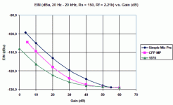
The "Simple" plan page 27... is Dotneck's console almost exactly. The EIN falls off badly at less than max gain. Yes, the THD may not stink at max gain, so run it wide-open until it smokes.
A CFP plan looks pin-compatable but needs all different resistor values to get better performance; particularly that pesky pot.
A full Wurcer/Cohen amp is not a heap better on hiss at maximum gain, but hiss does not rise so fast at low gain, and THD stays low.
Attachments
Excellent article---thanks so much for the link!! The CFP plan actually looks do-able; I DID find a 2.5K reverse-log pot @ Mouser----just have to see if it'll fit. The CFP, of course, is not ideal, but it does look like it could fit, and offers (from 0-30 db gain) a ~5db improvement of noise and ~26 db THD improvement---which is a LOT!! Hmmmm....
I am trying to wrap my head around the CFP preamp mentioned in post #12 above.
How do transistors Q3 and Q4 operate? They seem to have a dramatic effect on THD performance.
Best transistors for this application would appear to be ZTX690B/790A (rbb' of 5Ω; Hfe of ~400).
How do transistors Q3 and Q4 operate? They seem to have a dramatic effect on THD performance.
Best transistors for this application would appear to be ZTX690B/790A (rbb' of 5Ω; Hfe of ~400).
Last edited:
My take:
The internal 're' of Q1 and Q2 is current dependent, varies with current, producing distortion. Q3 and Q4 ensure collector currents thru Q1 and Q2 is a constant 1mA (Vbe/750ohm). Linearizing Q1 and Q2 b/c now 're' is more constant.
The resistors to -Vee set the total current to ca 5mA, the remaining 4mA goes thru Q3 and Q4.
I hope I understood it correctly...
I agree. You don' t need super duper low rbb' and high Hfe is good to have.I am trying to wrap my head around the CFP preamp mentioned in post #12 above.
How do transistors Q3 and Q4 operate? They seem to have a dramatic effect on THD performance.
Best transistors for this application would appear to be ZTX690B/790A (rbb' of 5Ω; Hfe of ~400).
I suggest you try transistor matching to get rid of the large cap at the gain resistor.
You do not need super duper low offset output. All you need actually is, low enough considering headroom.
...the CFP preamp ... How do transistors Q3 and Q4 operate? They seem to have a dramatic effect on THD performance.....
The single transistor, the emitter impedance is 26 Ohms at 1mA and varies directly with current. So with signal level.
The Sziklai pair, that emitter impedance is divided by the current gain of the second transistor, so can be under 1 Ohm. And, as SemperFi says, more constant because the second Q handles current swing and the first Q runs nearer constant current.
I think it is a half-way measure, but as the paper shows, it is good for 10dB-15dB better performance in some of the operating gain range.To get the hiss better it does need smaller resistors and pot.
I am thinking you are referring to Beta matching. How close do you think they need to be?I suggest you try transistor matching to get rid of the large cap at the gain resistor.
10% Beta matching.I am thinking you are referring to Beta matching. How close do you think they need to be?
1mV Vbe matching.
0.25°C Temp matching.
Just a suggestion to try this CFP topology without the large cap at the gain pot.
- Home
- Design & Build
- Parts
- Best microphone transistor

