LineSource said:...Matching transistors is a challenge for small quanitity DIY purchases, so I tend to use dual transistors and purchase binned parts. Thermal tracking is also much easier with duals.
Hi LineSource
For jfet it is very difficult to match but for bjt it is not that difficult ... or maybe I was lucky with my local store. Thermal tracking is interesting though. Do you know some dual bjts that can be used in diff input stage?
Thanks
lumanauw said:Hi, Mike,
Somehow I'm thinking about using very low Hfe like MPSA42 for differential. What bad thing could happen?
Hi lumanauw, using low hfe-devices for diffamp results in largely
increased inputoffset and very low inputimpedance.
The inputoffset is no problem if you use symetrical ltp.
The low inputimpedance can cause problems like reduced functionality
of feedbackloop, increased distortions, dynamic phaseshifts.
The mainproblem is, that you get a dynamic inputimpedance depending
on the signal flowing inside the ltp. In other words, you get a copy
of the feedbackerrorsignal into the input...
For symetrical ltp you would create 3rd harmonics and for "singleended"
2nd harmonics.
I have very good results with the hfe-monster "mpsa18"...
Mike
Best Input differential
How about this one?:
http://www.diyaudio.com/forums/showthread.php?postid=507432#post507432
😎
How about this one?:
http://www.diyaudio.com/forums/showthread.php?postid=507432#post507432
😎
hi fab
I think using a resistor as a current sourse isn't that bad.
OK, it has times lower CMMR, but active current sources suffer all 'active' imperfections. I mean simple one creates a pole at HF because of base-collector capacitance and cascoded current source is likely to be instable at VHF. All cascode designs may have problems in closed loop because they are complex and add much phase shift at VHF.
regards
Thanks everyone very very much for giving valuable comments and discussing the various topologies of differentials.
As for my choice i would go for Symmetric Cascode loaded Fully JFET complementary differential.
Regarding our amplifiers input topology sorry for that , we cannot discuss our design engineering here in the forum.
regards,
Kanwar
As for my choice i would go for Symmetric Cascode loaded Fully JFET complementary differential.
Regarding our amplifiers input topology sorry for that , we cannot discuss our design engineering here in the forum.
regards,
Kanwar
So you are collecting ideas from the forum members but you won't discuss your own design.........................?Workhorse said:Thanks everyone very very much for giving valuable comments and discussing the various topologies of differentials.
As for my choice i would go for Symmetric Cascode loaded Fully JFET complementary differential.
Regarding our amplifiers input topology sorry for that , we cannot discuss our design engineering here in the forum.
regards,
Kanwar
🙄 🙄 🙄
Re: Best Input differential
Hi Elso
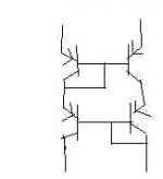
the LTP seems normal JFET cascode, but the whole design looks very strange. Folded cascode amplification bases on cerrent through emitter resistors and current mirror forces these currents to be equal... they are bankrupt now, aren't they?😀
Elso Kwak said:
Hi Elso
the LTP seems normal JFET cascode, but the whole design looks very strange. Folded cascode amplification bases on cerrent through emitter resistors and current mirror forces these currents to be equal... they are bankrupt now, aren't they?😀
Re: Re: Best Input differential
Hi darkfenriz,
What's strange? Or is this way over your head?
The current mirror is presenting a high impedance to the folded cascode stage and provides a differential-input to single-ended-output conversion........
Actually it works ............as a preamp.

darkfenriz said:
Hi Elso
the LTP seems normal JFET cascode, but the whole design looks very strange. Folded cascode amplification bases on cerrent through emitter resistors and current mirror forces these currents to be equal... they are bankrupt now, aren't they?😀
Hi darkfenriz,
What's strange? Or is this way over your head?
The current mirror is presenting a high impedance to the folded cascode stage and provides a differential-input to single-ended-output conversion........
Actually it works ............as a preamp.
lumanauw said:Hi, Mike,
Somehow I'm thinking about using very low Hfe like MPSA42 for differential. What bad thing could happen?
This is one of the reasons I have become partial to JFET input stages, and also increasingly MOSFET Vas. The extremely high input impedance helps isolate the nonlinearities of the different stages from each other. This is particularly helpful when driving difficult loads.MikeB said:...The mainproblem is, that you get a dynamic inputimpedance depending
on the signal flowing inside the ltp...
That looks unnecessarily complex to me. A JFET cacode, then a BJT cascode in the LTP followed by another (folded) cascode!Elso Kwak said:
Mr Evil said:
This is one of the reasons I have become partial to JFET input stages, and also increasingly MOSFET Vas. The extremely high input impedance helps isolate the nonlinearities of the different stages from each other. This is particularly helpful when driving difficult loads.
That looks unnecessarily complex to me. A JFET cacode, then a BJT cascode in the LTP followed by another (folded) cascode!
Hi Mr Evil,
Ain't that so
Omit the upper CB-pair
guess what, its get rot!
Don't you know the supply is 75 Volts hot!
http://borbelyaudio.com/home_theater.asp
Sorry Elso
In LTP it is not a mirror, it is kind of 'second common base' or 'dual cascode'. Everything's OK. My eyes must have been tired.
Nice avatar
regards
In LTP it is not a mirror, it is kind of 'second common base' or 'dual cascode'. Everything's OK. My eyes must have been tired.
Nice avatar
regards
Hi, Mr.Evil,
I always wanted to put MOSFET for VAS. But I have thinkings.
Usually I make differential only 2mA CCS (1mA/leg).
The MOSFET has inner capacitance 600pf-1nF.
For driving 1nF up to 100khz (ideally) it needs much bigger than 1mA, isn't it?
How to drive MOSFET VAS from 1mA differential leg?
I am thinking about TO-220 mosfet like IRF9610, not IRFD
This is one of the reasons I have become partial to JFET input stages, and also increasingly MOSFET Vas. The extremely high input impedance helps isolate the nonlinearities of the different stages from each other. This is particularly helpful when driving difficult loads.
I always wanted to put MOSFET for VAS. But I have thinkings.
Usually I make differential only 2mA CCS (1mA/leg).
The MOSFET has inner capacitance 600pf-1nF.
For driving 1nF up to 100khz (ideally) it needs much bigger than 1mA, isn't it?
How to drive MOSFET VAS from 1mA differential leg?
I am thinking about TO-220 mosfet like IRF9610, not IRFD
lumanauw said:Hi, Mr.Evil,
I always wanted to put MOSFET for VAS. But I have thinkings.
Usually I make differential only 2mA CCS (1mA/leg).
The MOSFET has inner capacitance 600pf-1nF.
For driving 1nF up to 100khz (ideally) it needs much bigger than 1mA, isn't it?
How to drive MOSFET VAS from 1mA differential leg?
I am thinking about TO-220 mosfet like IRF9610, not IRFD
Hi LumanauW,
We have used Mosfets in VAS, but there are driven with emitter followers first to get sufficient large bandwidth.
regards,
Kanwar
You can get low capacitance MOSFETS which won't be particularly hard to drive. No harm in running the LTP at a high-ish current (5mA total or more) though, or you could use an emitter-follower to buffer it, as Workhorse suggested (also seen in D. Self's designs).lumanauw said:Hi, Mr.Evil,
I always wanted to put MOSFET for VAS. But I have thinkings.
Usually I make differential only 2mA CCS (1mA/leg).
The MOSFET has inner capacitance 600pf-1nF.
For driving 1nF up to 100khz (ideally) it needs much bigger than 1mA, isn't it?
How to drive MOSFET VAS from 1mA differential leg?
I am thinking about TO-220 mosfet like IRF9610, not IRFD
Hi, Mr.Evil,
How to calculate the bias needed in differential for driving IRF9610 perfectly up to 100khz?
How to calculate the bias needed in differential for driving IRF9610 perfectly up to 100khz?
Looking at the datasheet for that one, it says 170pF input capacitance, which might not present a load to the LTP at high frequencies any worse than a BJT, since that internal capacitance would probably allow you to use a much smaller external Miller compensation capacitor, or even none at all.lumanauw said:Hi, Mr.Evil,
How to calculate the bias needed in differential for driving IRF9610 perfectly up to 100khz?
But to work out how much current you need, first work out the maximum slew rate you need (differential of the since wave at zero crossing), then the peak current needed to charge the input capacitance I = C dV/dt
Clearly you need at least that much current in each half of the LTP or it will be completely unable to drive the MOSFTET that fast, but for the charging current to have no effect, you need infinite current. Somewhere between those two values is a good compromise😀
Hi workhorse!! Have you chosen the best diff input stage yet ?
🙂
I also know which topo is the best . I have just built a amp with current mirror . I found that A normal current is worse than that current mirror . I don't its name
🙂
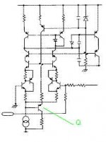
The document say that Q transistor will increase CMRR . I simulated it but it can't improve any thing and even distortion also increaseAnd here we go...
Go ahead and use it Kanwar, your amplifiers are going to be superiors and make a breakthrough, with this diff stage you don't need to bother anymore, but don't ask me for permision because I am the wrong person to do so!
Cheers
Ultima Thule has attached this image:
Click the thumbnail to see the original image.
I also know which topo is the best . I have just built a amp with current mirror . I found that A normal current is worse than that current mirror . I don't its name
Attachments
- Status
- Not open for further replies.
- Home
- Amplifiers
- Solid State
- Best Input differential configuration in amplifiers.