The boring answer to that question is: best for what??? They all have their uses and their pros and cons.All guys are pouring the differential designs from every corner of the world, but wait a minute could you all please tell me "Which one is the Best differential"
I like to go with as simple as possible for a certain funktion and maximize the circuit by using the right amount of current,local feedback and so forth.
Circlomanen said:
The boring answer to that question is: best for what??? They all have their uses and their pros and cons.
I like to go with as simple as possible for a certain funktion and maximize the circuit by using the right amount of current,local feedback and so forth.
Circlomanen, look at your Silly way of answering the question, which I think you dont even figure out what to ask for or what to say for it. maybe you dont know the answer. Dont worry other guys here would help me.
i again repeat"what would be the best differential to be implemented in amp circuit"
Im sorry if I offended you in some way, Im not trying to make fun of you or anything. But the answer is still the above. There are a million ways of building an amp and they are good at a million different things, soo, you are right! I dont know the answer to that question. I wish I knew! Than i would imediatly start a company producing amps. A normal simple diff pair is very good in many ways but not the absolut in lowest distortion, a more complex version can have a lot less distortion but not sound better anyway, and complex circuits often need more caps and stuff to make them stable and good behaving. I myself like CFP circuits because of the stability. they very rarly need any millercaps or any other kind of frequency limitation to be stable and yet they often offer very high bandwiths and high speed.Circlomanen, look at your Silly way of answering the question, which I think you dont even figure out what to ask for or what to say for it. maybe you dont know the answer. Dont worry other guys here would help me.
Transformers have a lot of good sides to, but they are not that popular.
If you specify the intended use, it will be a whole lot easier answering your question.
Johannes.
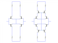
My favourites would be the ones the attachment. The one on the left is the simplest symmetrical LTP possible.
Circlomanen is right though, there is no single 'best' configuration. All have strengths and weaknesses that make them more or less suited to a variety of design goals and philosophies.
Circlomanen is right though, there is no single 'best' configuration. All have strengths and weaknesses that make them more or less suited to a variety of design goals and philosophies.
Attachments
Hi Mr Evil,
is that your bootstrapped cascode?
Could you produce a paper / wiki on the design process to arrive at the components around it to suit a set of input/output conditions?
is that your bootstrapped cascode?
Could you produce a paper / wiki on the design process to arrive at the components around it to suit a set of input/output conditions?
amplifierguru said:Hi Fab,
Just joking. "How may devices does a front end need..." ( to the tune of "Blowing in the Wind" Bob Dylan). But you forgot the IDEAL current source - surely that's good for at least 2 BJTs and a cascode.
Hi amplifierguru,
some peoples prefer a simple resistor for current source but I can not figure why (electronically speaking). Last one I used was 2 bjts with one resistor in series (in lieu of cascode bjt).
How to choose the suitable transistor for differential? One guru here said to choose one with big hfe.
Assuming max voltage and max dissipation is not a problem
MPSA06 Hfe=100
MPSA18 Hfe=400
MPSA42 Hfe=25
2N5551 Hfe=60
BC550C Hfe=420
The lowest Hfe is MPSA42, the highest is BC550C, which is the most suitable and most not suitable for Differential? And for VAS?
Assuming max voltage and max dissipation is not a problem
MPSA06 Hfe=100
MPSA18 Hfe=400
MPSA42 Hfe=25
2N5551 Hfe=60
BC550C Hfe=420
The lowest Hfe is MPSA42, the highest is BC550C, which is the most suitable and most not suitable for Differential? And for VAS?
Hi Kanwar,
I'm quite enamoured of chip front ends - you get defined performance (sometimes), monolithic matching and tracking and usually a DC offset adjust. Add lot's of gain and GBW defined to exchange for low distortion in the not so good output stage which is optimised for other parameters. All for a couple of $.
I'm quite enamoured of chip front ends - you get defined performance (sometimes), monolithic matching and tracking and usually a DC offset adjust. Add lot's of gain and GBW defined to exchange for low distortion in the not so good output stage which is optimised for other parameters. All for a couple of $.
How to choose the suitable transistor for differential? One guru here said to choose one with big hfe.
I think that should be modified to be "big minimum hfe". I'm reminded of the observation in Horowitz & Hill that a design that relies on a value of beta is a poor design. I presume that they actually meant a value greater than the minimum spec.
Yes I'd be inclined to agree with that for a commercial product Sam. But DIY has different rules - and high beta selection can be a simplifier so choosing from a group different hfe for different roles is a viable option.
I have a design nearing completion (150W/8ohm monoblock) which uses 5 pairs BC546/56 - some for regs,some for cascode, some for gain AND some for DRIVERS! I can select hfe ranges for each role and the reg or cascode comes well down the list so all devices are used 'gain'fully.
I have a design nearing completion (150W/8ohm monoblock) which uses 5 pairs BC546/56 - some for regs,some for cascode, some for gain AND some for DRIVERS! I can select hfe ranges for each role and the reg or cascode comes well down the list so all devices are used 'gain'fully.
kanwar:
i again repeat"what would be the best differential to be implemented in amp circuit"
----------------------------------------------
the most balanced
i again repeat"what would be the best differential to be implemented in amp circuit"
----------------------------------------------
the most balanced
lumanauw said:
MPSA18 Hfe=400
2N5551 Hfe=60
Lumanauw, what devices do you have ?
I measure with these:
MPSA18 Hfe=980
2N5551 Hfe=160
They both sound very good...
Mike
It's just the normal way to use JFETs as cascodes, as commonly seen in cascoded current sources. A resistor between the two tails sets the tail current (calculated in exactly the same way as for a JFET current source) and then it's just like a normal LTP, with gain and output DC level determined by the load resistors.AndrewT said:Hi Mr Evil,
is that your bootstrapped cascode?
Could you produce a paper / wiki on the design process to arrive at the components around it to suit a set of input/output conditions?
Workhorse said:
Circlomanen, look at your Silly way of answering the question, which I think you dont even figure out what to ask for or what to say for it. maybe you dont know the answer. Dont worry other guys here would help me.
i again repeat"what would be the best differential to be implemented in amp circuit"
Workhorse, bad attitude.

I agree with Circlomanen, simple seems to be best.
You're supposed to be the PROFESSIONAL Audio man, why don't you tell us your PROFESSIONAL answer. 😕
i again repeat"what would be the best differential to be implemented in amp circuit
The reason no direct answer is forthcomming is becasusse there is no "best". Indeed, the question as stated is nearly a Koan.
(; gnikoj tsuj
And here we go... 😎
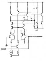
Go ahead and use it Kanwar, your amplifiers are going to be superiors and make a breakthrough, with this diff stage you don't need to bother anymore, but don't ask me for permision because I am the wrong person to do so! 😉
Cheers 😀
And here we go... 😎
Go ahead and use it Kanwar, your amplifiers are going to be superiors and make a breakthrough, with this diff stage you don't need to bother anymore, but don't ask me for permision because I am the wrong person to do so! 😉
Cheers 😀
Attachments
Hi, Mike,
Somehow I'm thinking about using very low Hfe like MPSA42 for differential. What bad thing could happen?
Somehow I'm thinking about using very low Hfe like MPSA42 for differential. What bad thing could happen?
Re: (; gnikoj tsuj
Hi Ultima Thule
This circuit look like the one in the Halcro patent us005892398.
Ultima Thule said:...this diff stage you don't need to bother anymore, but don't ask me for permision because I am the wrong person to do so! 😉
Hi Ultima Thule
This circuit look like the one in the Halcro patent us005892398.
Re: (; gnikoj tsuj Post #38
quote:
Originally posted by Ultima Thule
...this diff stage you don't need to bother anymore, but don't ask me for permision because I am the wrong person to do so!
Hi Ultima Thule
This circuit look like the one in the Halcro patent us005892398.
It looks like something ginned up at Digikey to sell more components.

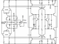
I would appreciate constructive feedback on symmetrical folded cascode front-end circuits similar to the attached +/- 12V schematic. Low noise and low distortion, espeically for the first watt are most important. Fewer transistors often translates into lower noise. Improvements to the basic design welcome.
Matching transistors is a challenge for small quanitity DIY purchases, so I tend to use dual transistors and purchase binned parts. Thermal tracking is also much easier with duals.
Matching transistors is a challenge for small quanitity DIY purchases, so I tend to use dual transistors and purchase binned parts. Thermal tracking is also much easier with duals.
Attachments
- Status
- Not open for further replies.
- Home
- Amplifiers
- Solid State
- Best Input differential configuration in amplifiers.