I need to find free schematic/pcb software, amateur level. Needs to be simple and small learning curve. Main requirement is that it have a library with tube symbols, both on the schematic and the pcb side (sockets, etc.)
Would be good if it has standard output I can upload to a PCB prototype house.
Anything out there you guys like?
This is for PC, not Mac.
Would be good if it has standard output I can upload to a PCB prototype house.
Anything out there you guys like?
This is for PC, not Mac.
The two most common are DipTrace and Eagle. Eagle has more libraries of parts and is more of a standard but I find it to be less intuitive than DipTrace. Both have a decent learning curve but I was able to figure out DipTrace in a few hours after going through the tutorial.
lots of threads, use search?
diyAudio - Search Results
A community dedicated to helping everyone learn the art of audio. Projects by fanatics, for fanatics! - Search Results for free pcb software
KiCad is a recent freeware project with active development - I've looked at it but just didn't get the workflow model - I use Eagle, paid for the full license
IMO, unless you're doing a lot of digital stuff, where the libraries are halfway decent, the first thing to do is ditch all the libraries. Almost every error I've ever made with a PCB program was due to a bad library part. Nor do I like the default pad sizes they often supply. I like FreePCB because its open source. At first it isn't obvious how to do many things, but the program is actually quite powerful. TinyCAD is the editor that can go with it.
Hey, that Kicad looks rather nice as well- 3D rendering capability!
Hey, that Kicad looks rather nice as well- 3D rendering capability!
Last edited:
Kicad is amazing - I use it all the time. I believe there are many libraries of parts available for it, although designing your own parts is pretty easy. Fully standard Gerbers etc. for output. Totally open source and free.
Kicad
There appears to be a large valves (tube) library available on this site:
KICAD Libraries
Kicad
There appears to be a large valves (tube) library available on this site:
KICAD Libraries
IMO, unless you're doing a lot of digital stuff, where the libraries are halfway decent, the first thing to do is ditch all the libraries. Almost every error I've ever made with a PCB program was due to a bad library part.
Agreed. However, they always seems to have far more 'artistic' schematic symbols than I get around to designing - transistors with filled in arrows, nice curves etc. so I often tend to start with the existing ones and edit them.
JCX, I did that search and did not see much on how tube-friendly any of the software is.
CopperTop, thanks, that's what I was looking for, something with tube libraries already there. I don't do enough of this to warrant spending much time to create my own. Most of what I do is point-to-point, so I use schematic capture more than pcb layout.
CopperTop, thanks, that's what I was looking for, something with tube libraries already there. I don't do enough of this to warrant spending much time to create my own. Most of what I do is point-to-point, so I use schematic capture more than pcb layout.
Please accept the fact that learning PWB layout software WILL take a little effort and some time. Part of the process is just learning the jargon - even terms that seem to have well-defined meanings in common usage may have a much more restricted definition within a PWB program. You also must appreciate that a printed wiring board is much more than just a place to park your parts, and some of your frustration comes from the software's attempts to satisfy the many requirements of a system that is MUCH more complex than a few copper conductors running across a piece of plastic.
One thing that surprised me was the amount of time I spent doing "library work" - creating symbols and padstacks for the components I used - even though the programs came with extensive component libraries. In fact, I don't think any of the software publishers I used created their own libraries - they converted the component manufacturers' libraries to ther programs' format. Consequently, if you had, say, 5 kinds of TO-92 transistors (or any other class of component) in your layout, you could have 5 different pad shapes, sizes, and drill sizes. And - none of them are the preferred sizes used by your board etcher. I also redraft some of the schematic symbols. Not many of the low-complexity parts like opamps or transistors, but I often re-arrange the pins on higher-integration parts like SMPS controllers or microcontrollers, so the visual presentation does a better job of communicating the component's function and the circuit designer's intent.
I have done boards using 4 different commercial programs. Each is different, but I would be hard pressed to say that one is truly "superior" to the others. Each required some practice and learning time before I could do really high-quality work with it - even though I had previously used other programs. I was always able to get help from online support forums, both company-sponsored and unofficial.
I haven't used any of the no-cost or hobby-oriented layout software. (I have one of the expensive (but rather outdated) commercial packages, courtesy of some consulting work I did several years ago.) I have noticed that many hobbyist and part-time freelance designers like the "Eagle PCB" program from Cadsoft. It's available in a variety of capability levels, with prices ranging from "no cost" to a few thousand dollars a copy (that's CHEAP by commercial standards!). Many hobby users have created tutorials and Youtube videos to help other users. "Kicad" is another popular package, developed as an open-source project. I believe the Student Version of "Multisim" also allows you to create simple PWB layouts.
And . . . you may want to look at "Latest version of PCBCAD40 now here.", on this Forum!
Although a few vendors who specialize in quick-turn, run-of-the-mill prototype boards require you to use their own no-charge, proprietary, on-line layout software - the "real" board vendors will require Gerber plotting files and an Excellon drill file. Fortunately, everybody in the industry knows this and all the PWB layout packages can produce these files. (Having said that, there are several variations of "Gerber files" and you'll need to find out from your board fabricator exactly what he's expecting and adjust the options in your PWB software accordingly. The "Gerber file" format itself has an interesting history dating back to the 1960's - long before it was used to fabricate printed wiring boards.)
Dale
I have been using Eagle since Version 2.6 which ran in DOS on an Intel 286 PC. I currently have the full version and there is a "tubes" library on their web site.
Eagle is the name of the program sold by the German company Cadsoft. Cadsoft was recently acquired by the component distributor Newark / Farnell. They released a new version of Eagle that can print out a BOM with Newark / Farnell part numbers. Newark / Farnell has built a forum / web site for engineers and technicians called Element 14.
Allied Electronics has been trying to play catch up as a distributor for a few years. They also put together a forum / web site called Design Spark. Design Spark is offering a completely free PCB layout package that is supposed to be capable of reading Eagle libraries and possibly Eagle designs. Since I already use Eagle, Cadence, and Mentor Graphics PCB tools I have not tried the Design Sperk tools because it will give me another set of commands to learn and remember.
DesignSpark | The gateway to online resources and design support for engineers
It's only to make the part yourself. It has nothing to do with tubes really. It's essential to know how to make schematic and layout symbols.JCX, I did that search and did not see much on how tube-friendly any of the software is.
CopperTop, thanks, that's what I was looking for, something with tube libraries already there. I don't do enough of this to warrant spending much time to create my own. Most of what I do is point-to-point, so I use schematic capture more than pcb layout.
DGTA,
EverythingPCB is a good starting point to look for software for free schematic/pcb and related software:
http://www.everythingpcb.com/p12171.htm
* PCB Layout / Design / Schematic Capture / Autorouting Software
* Demo, Shareware, Freeware & Trial Offer Software
* Design for Fabrication / PCB Design Validation
* EDA Simulation & Related Software
* Electromagnetic Simulation
* Gerber Editors / Viewers, Data Conversion & Translation Software
* Signal Integrity / EMC, EMI & EM-Modeling Software
A comprehensive list of EDA software and Tools.
http://www.eevblog.com/forum/index....96040d9fc63db7e74b86a6500&topic=3677.msg48998
For libraries read this:
http://www.eevblog.com/forum/index....96040d9fc63db7e74b86a6500&topic=3677.msg48998
Basicly IPC-7351, IPC-7352 if you follow these guidlines you wont go wrong.
http://www.eevblog.com/forum/index....96040d9fc63db7e74b86a6500&topic=3677.msg48998
For libraries read this:
http://www.eevblog.com/forum/index....96040d9fc63db7e74b86a6500&topic=3677.msg48998
Basicly IPC-7351, IPC-7352 if you follow these guidlines you wont go wrong.
kicad for windows7Kicad is amazing - I use it all the time. I believe there are many libraries of parts available for it, although designing your own parts is pretty easy. Fully standard Gerbers etc. for output. Totally open source and free.
Kicad
There appears to be a large valves (tube) library available on this site:
KICAD Libraries
Using free pcb software can be a false economy.
You cant beat pcbcad with good comprehensive error checking.
Nothing worse than getting pcbs made and there are mistakes on them.
You cant beat pcbcad with good comprehensive error checking.
Nothing worse than getting pcbs made and there are mistakes on them.
+1 for DesignSpark that was briefly mentioned earlier. I was a bit hesitant at first but having just completed a 1500+ part mixer I can honestly say that its got 100% of what you need and 99% of what you'd like. As for libraries, I always create my own 'cause third party ones although generally accurate don't share a common style and can look scruffy when mixed.
Also check out 'Free LP Viewer' from Mentor, and 'PCB Design Tutorial' www.alternatezone.com/electronics/files/[B]PCB[/B]Design[B]Tutorial[/B]RevA.pdf
Rob
Also check out 'Free LP Viewer' from Mentor, and 'PCB Design Tutorial' www.alternatezone.com/electronics/files/[B]PCB[/B]Design[B]Tutorial[/B]RevA.pdf
Rob
hello dgta
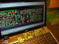
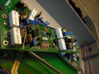
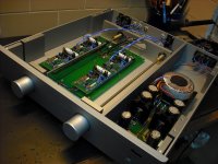
I use Altium Designer. simply the best we had today. All my prototypes are made by this software.
link:
Altium | AD10
My latest prototype (pre amplifier using a personal topology ) was this pre amp that I attach a photo
I use Altium Designer. simply the best we had today. All my prototypes are made by this software.
link:
Altium | AD10
My latest prototype (pre amplifier using a personal topology ) was this pre amp that I attach a photo
Attachments

Last edited:
All of the proffesional packages will do the job, I use Cadstar #1, then Allegro when I have to, but are a expensive option for hobby use (We pay nearly £8K maintenance just on EDA software).
The problem is to find a free or reasonably priced package that will cater for DIYers going into digital designs, as with the decent free packages you have limited pins and layers, which can be a big limitation in digital design. I have had a play with a couple of the free packages (Eagle and the RS offering and found them OK).
The problem is to find a free or reasonably priced package that will cater for DIYers going into digital designs, as with the decent free packages you have limited pins and layers, which can be a big limitation in digital design. I have had a play with a couple of the free packages (Eagle and the RS offering and found them OK).
- Status
- Not open for further replies.
- Home
- Design & Build
- Software Tools
- Best free schematic/pcb software?