A first, it would be nice if you explained what kind of tube it was on your picture, and in which regime. Looks like something starving if it was a real tube, or some lousy model. In both cases. I saw recently Lineup's sim with zero THD. It's even not funny.
Here the schematic.
The tube is not really pushed hard , and the model
seems to be well correlated to real life behaviour
of the said device..
Attachments

The right way to go.
Here is a different way, without output transformer:
Here I see the tube taking the place of a single junction EF , coupled to a class A room heater 😀 (hybrid FET/BJT 😱) with a DC servo to keep it all together.
I would consider the tube .... but as a line level preamp buffering my DAC (from my soundcards SPDIF). The power stage would still have to be AB (no AC - 36C here tomorrow 😉 ) .
I saw recently Lineup's sim with zero THD.
I know this could never be true. Simulations will show PPM , but the real thing will be .005 - .01% , depending on layout and quality of power supply. Lately I have considered PIM/TIM as factors that are as important (if not more) than just raw super low THD. Durability , scalability , and how sensitive the design is to component variations are also on my checklist.
OS
Lousy model of lousy tube on less than 1 mA idle current loaded on 120K, not on 10 MOhm as you wrote. Plus, 680 Ohm in cathode is really a feedback by current that makes spectrum of distortions wider. This tube was cheap and popular for guitar amps. Now it is expensive, because of demand of guitar players. I don't like it.
Try trioded 6J5P like I posted above, with LED in cathode, and gyrator in anode as shown. You can use 6AC7 model, but I doubt it is close to a real tube.
What is most significant in triode SE stages, distortions are of very low order, and go down and only down with lower signal levels. And tubes unlike SS devices don't care which frequency how to distort. Yes, Miller capacitances reflect amplification coefficient changes, but they are not so horribly variable like in real FETs.
However, tubes don't have such transconductances like FETs. SiC JFETs are nice devices for output stages, but I still would not use them in common source mode, if to speak about High-End.
Here I see the tube taking the place of a single junction EF , coupled to a class A room heater 😀 (hybrid FET/BJT 😱) with a DC servo to keep it all together.
No, it is actually 2-stage tube amp with feedback by voltage around them, with room heater output. Room heater is quite effective, because it is loaded on a counter - modulated current source. The full version is made of an augmented source follower, it wastes even more power in heat.
But it is the matter of taste: either to go with zero crossover distortions and dissipate 20 watt per channel on heatsinks, or to go with "more effective" design, and in order to minimize audibility of cross-over distortions dissipate 200W per channel on speakers.
And tubes unlike SS devices don't care which frequency how to distort.
??? Like... they don't distort more with increasing frequency? Or... their distortion spectra remains constant with frequency ?
OS
Lousy model of lousy tube on less than 1 mA idle current loaded on 120K, not on 10 MOhm as you wrote. Plus, 680 Ohm in cathode is really a feedback by current that makes spectrum of distortions wider. This tube was cheap and popular for guitar amps. Now it is expensive, because of demand of guitar players. I don't like it.
Try trioded 6J5P like I posted above, with LED in cathode, and gyrator in anode as shown. You can use 6AC7 model, but I doubt it is close to a real tube.
What is most significant in triode SE stages, distortions are of very low order, and go down and only down with lower signal levels. And tubes unlike SS devices don't care which frequency how to distort. Yes, Miller capacitances reflect amplification coefficient changes, but they are not so horribly variable like in real FETs.
However, tubes don't have such transconductances like FETs. SiC JFETs are nice devices for output stages, but I still would not use them in common source mode, if to speak about High-End.
Will do a few sims to check the tube you re quoting..
As for degeneration in the test schematic, well, degeneration
extend the THD spectrum but reduce its total value,
so it s a double hedged sword wether you use it or not.
The beauty of SS devices is that what is lost using
reduced degeneration is more than balanced thanks
to the higher available global NFB, while with tubes
there s nothing like this , at least not as efficiently
and as easy to implement, so degeneration is a must do...
But it is the matter of taste: either to go with zero crossover distortions and dissipate 20 watt per channel on heatsinks, or to go with "more effective" design, and in order to minimize audibility of cross-over distortions dissipate 200W per channel on speakers.
I agree , every class AB strives to be a perfect A. Xover distortion and (how) the AB stage yanks the charge out of the "switched off" device determines the fidelity of the amp as a whole. I've perfected my 3 voltage stages , but the OP stages are the weakest link. I know this, because I have a "room heater" to plug my voltage stage modules into 😀 .
The Japanese OEM's have all sorts of engineering tied up in the AB OP stage. "super A" " hyperbolic OPS" .... many extra devices just to "tame" that small region .
OS
In your opinion what type of amplifier sounds best , Class A tube amp or others ?
My best amp. Mosfet amp, 5 pairs IRFP240/9240
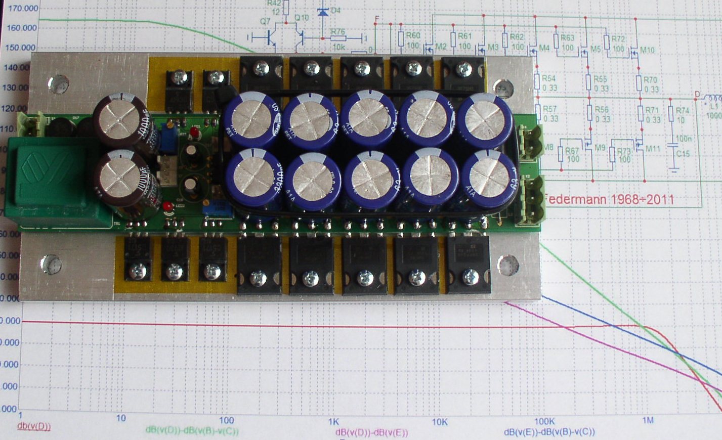
The power 10x3.3mF/63V
??? Like... they don't distort more with increasing frequency? Or... their distortion spectra remains constant with frequency ?
They don't have Early and Kirk effects, they don't have base width modulation, they don't have non-main charge carriers, their thermal time constants are relative huge, and so on.
Hello,
This thread started out in a fun way, but seems to have died in a tube vs solid state standoff.
Alltho I created my account in '05, I've just been reading here every now and then, and only last month I decided to start getting serious with my audio hobby. So I started to collect the gear for a little lab, I still have to start my actual first project. This to point out I'm as new as they come to this topic.
When reading about audio equipment online over the years, the devision in the audio world in an audiophile camp and a techical specs camp has hugely boggled me. Who is right and why, I can't get my head wrapped round it.
What I read from Wavebourn in this thread I found hugely interesting. That an amplifier with distortions that occur in nature, but without distortions that not occur in nature sound good. That distortion that in/decreases with the amplitude of the output sounds good. That this distortion pattern is linked to a smooth transfer function of the amplifier. That the filters in our ear/brain system take good care of the natural distortions so we don't register them. It's the first thing I've read that makes sense, intuitively, to link both audiophile and tech spec camps together.
Therefore, I'd like to ask a few questions to help me understand better.
Would it be possible for you, Wavebourn, to post 2 transfer functions, one of a good sounding high end amp, and one of a uberlow THD linear "dead" sounding amp, and point out where the low THD transfer function goes wrong to your opinion?
Are transfer functions additive, by which I mean that:
TF(amp) = TF(inputstage) + TF(VAS) + TF(outputstage)
so that you can analyze parts of an amplifier to get to a good final result.
As asked twice before by AKSA, I'd also like to see opinions related to image depth with regard to the amplifier used as well, even tho I suspect that this is much more a thing governed by speaker/room setup.
My goal is to build an high end system for a hifi price. I'd rather get there in 2/3 projects instead of 20/30. I feel that what's discussed here could give me design rules to follow that will speed things up greatly, so any input is hugely appreciated.
Regards,
René
Are transfer functions additive, by which I mean that:
TF(amp) = TF(inputstage) + TF(VAS) + TF(outputstage)
so that you can analyze parts of an amplifier to get to a good final result.
Hi René;
a first,
TF(amp) = TF(inputstage) * TF(VAS) * TF(outputstage)
So, if all of them were of the 2'nd order only (hypothetically, of course), which order will be TF(amp) as the result?
Now we are back to "one vacuum triode VS many transistors with feedback around them" topic. 😉
- Status
- Not open for further replies.
- Home
- Amplifiers
- Solid State
- Best Amplifier Sound