Having listened to both Nickel %50 ie Perma 50 and Nickel %78 MU Metal there is a difference in sound regardless if they are C core EI cores with the purity of metal is the most important .
For instance I have Double C cores Perma 50 with pure Silver Primary and Secondaries just like Kondo Ongaku Perma 50 then the %78 Nickel EI 96 cores with OCC copper sound better IMHO , I know AN UK will differ on this ie IE v C core Nickel and used to charge a fortune for their C core and silvers , Large EI96 Nickel %78 & OCC copper wire suited me and more natural sounding , so a great deal of Hype around the Ongaku , low vibration capacitors etc , you would need to actually hear these products before believing any of the reviews that generally come with lots of adds as part of the deal .
For instance I have Double C cores Perma 50 with pure Silver Primary and Secondaries just like Kondo Ongaku Perma 50 then the %78 Nickel EI 96 cores with OCC copper sound better IMHO , I know AN UK will differ on this ie IE v C core Nickel and used to charge a fortune for their C core and silvers , Large EI96 Nickel %78 & OCC copper wire suited me and more natural sounding , so a great deal of Hype around the Ongaku , low vibration capacitors etc , you would need to actually hear these products before believing any of the reviews that generally come with lots of adds as part of the deal .
Last edited:
He was getting really spicy in another thread and got moderated. Don’t know if he was banned or if he left in a huff. Neither would surprise me.Wonder what happened to 45, says "account closed"; I valued their input. The lower % Nickel cores look interesting
Thanks,
I need to do some reading to brush up on my understanding so apologies for dumbness and lazyness on my part. What little I know about transformers has faded from memory.
I imagine for 78% vs 50% Nickel, a much bigger core would be needed for 78% to reach the same LF roll off. But as a starting point how much bigger % size core are we talking. Have you posted photos; I haven't read all the posts here nor that "show me your iron/winding thread"; (it's on my to do list). If so could you please point me to them.
I used to think that as a general rule bigger cores lead to poor HF response but then realised/ was informed that is not true and in truth that good HF can be attained with big cores; budget permitting being the constraint.
I gather 50% is available in c-core but the higher % Nickel types are (generally) only in EI. Is that right.
Silver must be mighty expensive, if I recall the silver vs copper conductivity is only a small % difference. I would have assumed tight winding making full use of the window, correctly sized teflon/paper, and square wire would have bigger impact than silver. Does skin effect come into play, wonder if silver plated magnet wire is available / worth considering. Only ever seen magnet wire in full copper round and occassionally square; never silver but clearly it is/was being manufactured somewhere. I did wonder if the varnish/enamal matters much, type & thinkness, is it a choice between polyester and polyurethane.
And then there is PI winding, have there been any recent examples/ testing/ designs done to see if this is a better compromise.
Last edited:

.....so I found enamelled 99.99% silver 1750USD/Kg, Silver plated for $100 and flat copper $30, round copper $15. Thats quite a difference.
Silver 7% more conductive than Copper, both have a T/C of around 0.39%, which got me wondering about the magnetic properties of the core materials at different temperatures. Visions of using a Peltier,heatsink and insulated metal-can come to mind as does condensation and HT. Does anyone have links to temperature relationship for core materials; I would assume the research exists.
Thanks
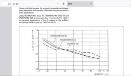
..... so I stumbled across this. Only quick scanned it, but seems to suggest (if I am reading it right?), that temperature a bit above ambient is optimum for the core. So I need to cook the core but not the winding.
See fig 11 on paper 24 or 26
https://vacuumschmelze.com/03_Documents/Brochures/PHT 001 en.pdf
See fig 11 on paper 24 or 26
https://vacuumschmelze.com/03_Documents/Brochures/PHT 001 en.pdf
Attachments
And then there is PI winding, have there been any recent examples/ testing/ designs done to see if this is a better compromise.
From a technical point of view, not worth it. Even tube amp chokes with an iron core, for most of the part need no more than two vertical splits. Otherwise, core to coil capacitance takes over, killing the idea.
As far as interleaving goes, you get the same capacitance vs leakage inductance laws. In PI interleaving, the leakage inductance decrease this time depends on the coil thickness, not length. So cores with a big window are prefered for PI interleaving.
My best idea with PI winding so far was stacking PCBs with trace windings to demonstrate different interleaving strategies with leakage inductance and capacitance distributions. You could stack, connect and demonstrate in a hurry. The idea was not yet put into practice due to time scarcity.
I used to think that as a general rule bigger cores lead to poor HF response but then realised/ was informed that is not true and in truth that good HF can be attained with big cores; budget permitting being the constraint.
Transformers with bigger cores are always easier to achieve a higher bandwidth, as core surface area increases by a square factor, compared to the Mean Turn Length of the core. With a bigger core, you need a lesser amount of primary turns to achieve the same leakage inductance value, then you can get less interleavings. And the little P/S interfaces you get, the more you can cheat to decrease capacitance by redirecting primary layers, getting better Ls * Cps ratios. Ideally, one can get zero primary to secondary layer capacitance with a single P/S interface.
The main limitations for bigger transformers are:
-Footprint
-Materials cost
-Finding available huge enclosures on the market. How often do you see potted 100W SE transformers in boxes?
-Probably the lack of strong lower back musculature in many audio enthusiasts, except for floorstand speaker builders.
Last edited:
I have used Parafeed Nickel Autoformers as discussed earlier and they work well and can be much smaller , but having said all of this through my journey I was happy with Double C HiB core and would not loose any sleep if I could no longer get any Nickel .
Remember you will need a stack of EI96 Mu metal about 5 kgs for a 2A3 as it saturates so quickly , Auto formers are the easiest way around this problem , but then your Anode Choke Load has to be excellent and very well wound for Audio use. I also found the coupling capacitor needs to be of good quality 3.9-4.7uF , metalized polyprops are fine as the signal level / current post the Anode Choke is quite high , you wont need to spend zillions to find something a 4.7uF / 600v Mundorf Mcap Supreme or a 3.9uF would suit, I actually found the bass response of a 3.9uF measured well in the final result and less sluggish sound more speed .
I hope my findings are useful and prevent others spending a lot of money trying all these core types in the hope of audio nirvana , Nickel mixed with M6 works well puts more meat on the bones .
Last edited:
I've now put my Ogonowski SE OPTs into my 2 stage amp and the results are very good. The best acoustic piano sound I've heard yet in my system. Smooth, plenty of detail, airy high end, and beautifully built. I recommend these OPTs without hesitation. Mine was 5K and optimised for 60mA. Just the 8 ohm tap on the output, but I'm sure you could specify whatever you need. Very happy with the quality and price and I'd go straight to Ogonowski if I needed another OPT.i looked at the Ogonowski website and the cheapest SE OPT is quite reasonable, $109. Says 2.5K so I'll ask about 3.5K and 5K.
https://www.ogonowski.eu/transformers/single-ended/lo-se25-5/
Did you order the special core Grid01 was talking about?I've now put my Ogonowski SE OPTs into my 2 stage amp and the results are very good. The best acoustic piano sound I've heard yet in my system. Smooth, plenty of detail, airy high end, and beautifully built. I recommend these OPTs without hesitation. Mine was 5K and optimised for 60mA. Just the 8 ohm tap on the output, but I'm sure you could specify whatever you need. Very happy with the quality and price and I'd go straight to Ogonowski if I needed another OPT.
Mine are SE25-5 5k/8R on the annealed cores CC HiB, thickness of laminations is
0,23mm price 160€ x 2=320€. They look like the picture.

0,23mm price 160€ x 2=320€. They look like the picture.
Hi all
Very nice
It'll be fine for a SE with SV811-10 in Class A2 15 or 20w expected
next projet... 😏
Very nice
It'll be fine for a SE with SV811-10 in Class A2 15 or 20w expected
next projet... 😏
Grid01,
Because that transformer works with a KT66 @ 43% UL all the way down to 20Hz (no negative feedback other than the UL tap),
Then . . .
A Triode wired KT66 will get even lower than 20Hz (no negative feedback, other than Plate to Screen [Triode Wired mode]).
Yes, there will be less power out versus UL power out.
At 25 to 30% of maximum output power of each mode, the distortion is:
Triode Wired: lowest
UL: medium
Beam power mode: highest.
And global, Schade, or cathode negative feedback is used on beam power mode, and often used on UL mode to reduce that distorion.
Triode Wired has the highest intrinsic damping factor,
UL is medium,
And beam power has very low damping factor.
That is one reason global or Schade negative feedback is used on beam power and UL modes.
Think:
If Screen is 43% UL,
Then Triode Wired is 100% 'UL',
and Beam Power is 0% 'UL'.
A Triode wired KT66 has a plate impedance, rp, of about 1300 Ohms.
A KT66 @ 43% UL has a plate impedance, rp, of about 2700 Ohms.
A KT66 in beam power mode has a plate impedance, rp, of about 22,000 Ohms.
Which operating mode can drive a 5,000 Ohm primary without using an extra form of negative feedback (something other than triode wired or UL)?
Some tradeoffs are:
Simplicity
Power level
Damping factor
Distortion
Extra forms of negative feedback, or no extra negative feedback
Whenever I purchase a first-time-new-to-me output transformer model, I always have fun employing it.
A Question for you output transformer experts . . .
How do the different core materials respond, versus the tube plate impedance, rp, that drives them?
Consider output transformers that are identical, except they have different core materials.
Does the plate impedance of 1300 Ohms, versus 2700 Ohms, versus 22,000 Ohms, have any different effect versus the core matterial?
If there is a difference, that could be one factor in what core material "sounds" best under differing conditions.
Last edited:
An increase of tube Rp ramps up the distortion in the bass region, where it fights against primary inductance, but there's also an increased distortion in the high frequencies, if the transformer is designed for a high shunt capacitance for the tube Rp.
There is a variation between distortion and signal level as well, due to the low-permeability due to core hysteresis. Nanocrystalline and high % nickel are better in this regard. At high levels, the distortion increases due to potential core saturation.
There is a variation between distortion and signal level as well, due to the low-permeability due to core hysteresis. Nanocrystalline and high % nickel are better in this regard. At high levels, the distortion increases due to potential core saturation.
In my small experience, I’ve found to like alot a lower than usual amount of UL together with Schade negative feedback:Some tradeoffs are:
Simplicity
Power level
Damping factor
Distortion
Extra forms of negative feedback, or no extra negative feedback
I chose the UL in the 20-25% range to have still pentode-like power but a way lower rp, then apply a small amount of Shade to reduce rp in the triodish range and linearize curves.
This configuration is simpler than pentode for the PSU, gives pentode-like power and triode-like rp and distortion without ither forms of feedback. The driving stage needs to be beefier to manage the steeper loadline of Shade kind of feedback.
UNSET kind of feedback, on the other side, in my experience doesn’t like to be combined with UL, and 10-20% can make almost every pentode become a triode while keeping pentode output power. The driving stage needs to be able to swing more volts.
Hi, this is my SE 300B amps built this year , sounding great, not yet measured but I'm pleased how it sound. I attach scematic and picture of finished amps. Output transformers are C4 core amorphus 3,5 K /4 and 8 ohm from Aliexpres.


Really nice. The core material should be comparable to the hashimoto 0.27mm Orient Core Hi-B(1.10 W/Kg loss) and the AN high B 0.23mm. Probably the best price/tonality OPTs available.Mine are SE25-5 5k/8R on the annealed cores CC HiB, thickness of laminations is
0,23mm price 160€ x 2=320€. They look like the picture.
View attachment 1362347
- Home
- Amplifiers
- Tubes / Valves
- Best 300B SE OPT?