
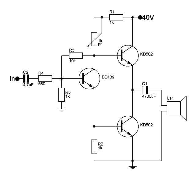
Thanks for all your propositions, what do you think about QUAD 405 with KD503 output transistors?
???????? ??????????? Quad 405-2. ??????
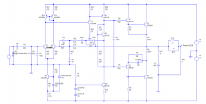
Here's the circuit I was thinking of.
Based on an old Bailey design, with some JLH70W and Blameless features.
Uses inclusive feedback, which JLH preferred, split to use transitional feedback to reduce crossover distortion as this is quasi. Note that the Bailey design needs a low impedance on the feedback side of the input diff pair (50 ohms) so the normal feedback resistor is split to give DC balance.
Simulated distortion .007% at 1kHz and .03% at 20kHz.
TIP3055 is used as this is a reasonable model, 3MHz. The KD503 seems to be like an MJ802, and should work just as well in practice, but I don't have a model for either.
Attachments
Nah, that KD503 is more like a 2N3772. If it’s the Tesla, it will be rugged enough but check them for voltage before running over 60V. That “Motorola” is as fake as fake gets. It will probably be good for well over 80 volts, but can’t do **** for current. Might do ok on +/-20V rails, where TIP41’s would actually suffice.
MJ4502’s are kind of a dog for ruggedness. Beta holds up at high current pretty well, but 2N5630 was a much better compromise.
MJ4502’s are kind of a dog for ruggedness. Beta holds up at high current pretty well, but 2N5630 was a much better compromise.
In the 1980's Maplin did a 225WRMS disco amplifier.
It used 2 pairs of 2n3055/mj2955.
It ran off about +/- 55 volts which was very brave.
I ran one for about 5 years and it took some stick but was very loud.
Some of the transisto5rs are obsolete now but modern equivalents could be found.

It used 2 pairs of 2n3055/mj2955.
It ran off about +/- 55 volts which was very brave.
I ran one for about 5 years and it took some stick but was very loud.
Some of the transisto5rs are obsolete now but modern equivalents could be found.
008080 specifically said he has a whole bash of the 3055's and he would like to use them. Hence my question about the version of 3055, and recommendation for the Bedini design. Might not have the absolutely best performance specs, but it could drive difficult loads with ease - and sounded bloody marvellous.
And it is reasonably simple design. Might be "olde" but still relevant.
And it is reasonably simple design. Might be "olde" but still relevant.
Last edited:
WGski - yes, I think Old DIY was trying to make the point that the "Moto" device is fake ... it looks like a tiny 3.5mm chip (at best, I haven't measured it) which would (at best) be an epi 3055 -alike. And probably with poor ISB devaluation. The "real" KD503 is a much bigger chip and probably OK for at least 150W.
The data sheet I dug up gave the Vceo of the 503 as 80V, and ft 2MHz. A 3772 has 200kHz rating (even epi devices still use that min. spec even if they are now 2MHZ).
That's why I think (if the device is genuine) it should be OK, but in a shortform listing there are no graphs and no indication of ISB limits. RCA only appeared to use selected 3772's for their 70W amp.
Nigel7557 - I recall thinking at the time that this amp should not work. IIRC it used BFY51's rated at 30V or something like that. The 2N3055 spec originally called for 70V Vcer, and while I successfully ran amps using RCA's 3055H at +/-35V, I did not consider going beyond until the epi devices came along. The original spec called for Vcbo of 100V. Unfortunately several imitation devices did not spec. Vcbo at 100V.
As I have often suggested, the epi devices could only match 100V with (old) technology if Vceo was much higher (e.g. 100V) so it would have been possible to (in theory) run an amp at +/-50V with epi devices but only if the bases were tied together with a bias resistor so that they were actively reverse biased, and not Vcer'd to the centre rail.
BUt, it appeared ON Semi (Motorola) and ST (when they made them) did manage to run at over 80V. I only ever used 40V rails for a 70W amp, but checking the Vceo on devices I used.
I don't know of large numbers of reports of Maplin's design blowing up, so it seems they "got away with it".
I suggest the drivers could be MJE15032/33 or similar, or (as this amp was often used with 4 ohm loads) a separate BD139/BD140 driver for each output.
However, the circuit is not what I would call "the best". It was designed to be rugged (ignoring the Vceo ratings of the transistors), and THD leaves a little to be desired for hifi. But perhaps OK for disco/bands where power trumps distortion.

check out this thread:
https://www.diyaudio.com/community/...dels-quasi-complementary-power-output.157430/I am looking for the first RCA advertisements and brochures of 2N3055.
https://www.diyaudio.com/community/...dels-quasi-complementary-power-output.157430/I am looking for the first RCA advertisements and brochures of 2N3055.
check out this thread (2N3055 vs. MJ150xx on JLH)
https://www.diyaudio.com/community/threads/jlh-10-watt-class-a-amplifier.3075/
https://www.diyaudio.com/community/threads/jlh-10-watt-class-a-amplifier.3075/
- Home
- Amplifiers
- Solid State
- Best 2n3055 amplifier