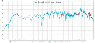
Is this graph below from the same REW measurement that you're currently using, except with a shorter gate? If so, I think the 70dB flat portion on here just might be the accurate baseline level for the woofer, although it would be nice to have more like 4ms clean than 2.6. Try swapping it in and see how your notch action looks on that response
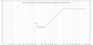
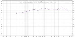
Yes, here it is below at 4ms.
I will try it and let you know. 🙂
Attachments
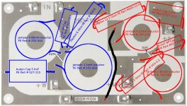
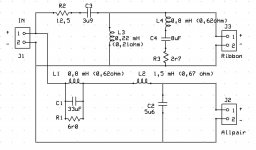
I spent most of today working on the board layout for the crossover using PE 260-132. See attached. Any mistakes please let me know.
You are going to want to rotate 2 of those coils so they don't inductively couple and skew your inductance values. Right angles to each other, and as if they would roll over the adjacent flat-laid coil. IE- the central axes of the coils should be in parallel planes, where one is going north-south, and the other is going east-west.
Make sense?
FWIW- I use pegboard and zip-ties/glue.
Later,
Wolf
You are going to want to rotate 2 of those coils so they don't inductively couple and skew your inductance values. Right angles to each other, and as if they would roll over the adjacent flat-laid coil. IE- the central axes of the coils should be in parallel planes, where one is going north-south, and the other is going east-west.
Make sense?
Looks like I have two things to do then. 🙂
You mean turn two of the coils on edge, right? Which two? I get it about having the edge of the coil facing the other one laid flat. Actually it crossed my mind but I was thinking space savings, nice to know there is a sonic reason as well.
Looks like I have two things to do then. 🙂
You mean turn two of the coils on edge, right? Which two? I get it about having the edge of the coil facing the other one laid flat. Actually it crossed my mind but I was thinking space savings, nice to know there is a sonic reason as well.
From left to right, either 1 and 3 or 2 and 4. I don't mean 'facing the other' either, as that can also skew components values.
Like this:

Later,
Wolf

I meant a new measurement without reflections until >4ms; the shorter gate is more helpful with your current measurement because it gives you a clean view of the diffraction effects in the 1k area, whereas any longer time introduces big reflection ripples there.Yes, here it is below at 4ms.
I will try it and let you know. 🙂
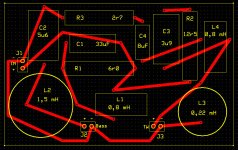
Maybe this will help you design a new layout.
The board is 160 x 100 mm.
0,8 mH inductors are placed vertically.
This is a top view and the wires run on the bottom side.
Thank you so much for your effort to help me it is appreciated. I did my last crossover point-to-point and I think I'd prefer the pcb. I'll study what you did here though.
I meant a new measurement without reflections until >4ms; the shorter gate is more helpful with your current measurement because it gives you a clean view of the diffraction effects in the 1k area, whereas any longer time introduces big reflection ripples there.
Ah. Well outside it's noisy here (although the noise is consistent rather than various) so I don't think I can do it outdoors even if I did have a speaker cable that long. 🙂 Maybe. Do you really think it's worth it? You are thinking these might not have enough bass if the baffle step is not fully compensated for I'd guess.
Baffle step might be ameliorated to the point of being benign, but it cannot be fully compensated. In other words you want to look at what's going on there to decide how to fix it.You are thinking these might not have enough bass if the baffle step is not fully compensated for I'd guess.
Ambient noise levels measured with a spl meter are about 56 dB indoors and 64 dB outdoors here. I did pick up a 50' speaker wire today and am thinking about testing outdoors if that would help considering the above....would be fewer reflections at least.
That's pretty high noise all right, but I think you'd be fine with good volume and some averaging. The measurement outside is still limited by distance from the ground, though. Before going outside, raise the speaker so the woofer is halfway between floor and ceiling, and measure the woofer from about 60 cm. That's too close to take single mic location measurements for xover design, but for on-axis of the woofer, differences from farfield should be maybe 1dB at worst.
With the closer distance to the mic and farther distance to the floor, you get a lot more ms of impulse before the first reflection (which should be floor and ceiling at once unless you're too close to something else, in which case, try not to be 😉).
With the closer distance to the mic and farther distance to the floor, you get a lot more ms of impulse before the first reflection (which should be floor and ceiling at once unless you're too close to something else, in which case, try not to be 😉).
Last edited:
Well I went ahead and did a set of outdoor measurements. It was not the most convenient thing in the world. 😀
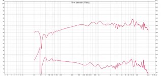
Attached are separate screenshots showing the woofer and then the tweeter. I did several sweeps of each driver, then gated each at 4ms and smoothed 1/12th octave then averaged them and that's what you're looking at here. The mic is approximately at tweeter height, 43.5" and 36" away.
Next after some rest I'll try the measurements with the crossover we designed.
Attachments
Last edited:
PS Here are the FRD files from the outdoor session above. I hope the phase is right, the averaged responses from REW did not have phase data but I extracted minimum phase in Response Modeler. I think it's OK.
Attachments
-
merged-alpair-smoothed-4ms-gated-min-phase.frd.txt12.7 KB · Views: 63
-
merged-rt1.3we-smoothed-4ms-gated-min-phase.frd.txt9.8 KB · Views: 54
-
merged-both-together-smoothed-4ms-gated-min-phase.frd.txt9.7 KB · Views: 49
-
markaudio-alpair-10.2_simmed_minphase.zma.txt13.2 KB · Views: 56
-
HiVi RT1.3_minphase.zma.txt2.2 KB · Views: 61
Last edited:
Well I went ahead and did a set of outdoor measurements.
It was not the most convenient thing in the world. 😀
And now is the time to take care of the standing waves, the axial
mode of the inner height being the most pronounced. It shows.
Can you upload the REW file instead? For averaging, you can just change the "sweeps" setting to 4 or 8 after you click "measure".
Last edited:
Can you upload the REW file instead? For averaging, you can just change the "sweeps" setting to 4 or 8 after you click "measure".
Ah, of course. In any case, here are one REW .mdat file for both the tweeter and the woofer. Raw, without smoothing or gating. Thanks.
https://www.dropbox.com/s/sglp281gwid3m71/alpair-3-Jun%2023%2015%2017_24_40.mdat?dl=0
https://www.dropbox.com/s/r3h48807zzaom5h/rt1.3we-1-Jun%2023%2015%2017_24_40.mdat?dl=0
- Status
- Not open for further replies.
- Home
- Loudspeakers
- Multi-Way
- Ben's "Hi-Marks" Fullranger + Isodynamic Tweeter 2-Way Build Thread