It will have internal +/-15V rails I suspect. This of course makes choosing devices easier and allows good headroom.
Hi,
This is quite an old thread, but since Behringer UCA222 are still sold today, it can probably be useful for some people to complete this discussion.
I've acquired one recently, and i've discovered this low frequency cross-talk problem by myself, so was seeking for any possible fix. The one proposed here is a great one, but i have some questions about it.
So the most efficient fix seems to be to provide a regulated voltage reference to op-amps. And to simplify the fix, to get it from the the PCM2902 (or supposedly its chinese clone V2902 in newer UCA222).
But:
Is it possible to avoid to loose monitor switch :
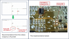
I've found these 2 videos, with the first one explaining and demonstrating the problem, and the second one proposing a solution by replacing R39 by a LM385-2.5 reference diode to create a better reference voltage for the op-amps, and also replacing C13 by a bigger 1000µF one.
With only 2 modifications, it looks even simpler than the fix proposed here. Nothing said about monitor switch, so seems to preserve this function.
Could it be a better solution than the one in this post? The best or is there better mod to make? Or are there some disavantages?
Thanks for your help.
This is quite an old thread, but since Behringer UCA222 are still sold today, it can probably be useful for some people to complete this discussion.
I've acquired one recently, and i've discovered this low frequency cross-talk problem by myself, so was seeking for any possible fix. The one proposed here is a great one, but i have some questions about it.
So the most efficient fix seems to be to provide a regulated voltage reference to op-amps. And to simplify the fix, to get it from the the PCM2902 (or supposedly its chinese clone V2902 in newer UCA222).
But:
In which way the monitor switch will no longer work: no more monitor function, or permanent monitoring?- remove R14 & R21 (required because of direct coupling in the monitor signal path, the monitor switch will no longer work)
Is it possible to avoid to loose monitor switch :
- by using the existing reference voltage, but doing modifications differently and adding other components?
- by NOT reusing the existing regulated voltage, but instead adding a new reference voltage source? Which one and how?
I've found these 2 videos, with the first one explaining and demonstrating the problem, and the second one proposing a solution by replacing R39 by a LM385-2.5 reference diode to create a better reference voltage for the op-amps, and also replacing C13 by a bigger 1000µF one.
With only 2 modifications, it looks even simpler than the fix proposed here. Nothing said about monitor switch, so seems to preserve this function.
Could it be a better solution than the one in this post? The best or is there better mod to make? Or are there some disavantages?
Thanks for your help.
Forgot to include links to the videos:
Default analysis:
Proposed fix:
There are in german, and Youtube's automatic translation is not so good, but they are interesting.
Default analysis:
Proposed fix:
There are in german, and Youtube's automatic translation is not so good, but they are interesting.
Normally the analog outputs of the UCA202/222 are driven by the digital signal coming from the computer. The monitor function allows the analog input to be routed directly to the analog outputs, thus bypassing delay from ADC/DAC signal conversions and processing in the computer. This could be useful for pro-audio environment where any delay or latency between input and output used for monitoring yourself performing might be unacceptable. But for audio measurement setups, I can't think of any reason for needing the monitor switch.In which way the monitor switch will no longer work: no more monitor function, or permanent monitoring?
For this modification I wanted to remove all reference voltage related crosstalk between the analog output and input sections so I chose to use a separate reference voltage for the input section. The ability to route the analog inputs directly to the outputs was removed because the signal path for the monitor function was direct coupled and keeping it would result in DC offset since the reference voltages were not exactly the same for the input and output sections.
Thanks for the video links 🙂Is it possible to avoid to loose monitor switch :
- by using the existing reference voltage, but doing modifications differently and adding other components?
- by NOT reusing the existing regulated voltage, but instead adding a new reference voltage source? Which one and how?
I've found these 2 videos, with the first one explaining and demonstrating the problem, and the second one proposing a solution by replacing R39 by a LM385-2.5 reference diode to create a better reference voltage for the op-amps, and also replacing C13 by a bigger 1000µF one.
With only 2 modifications, it looks even simpler than the fix proposed here. Nothing said about monitor switch, so seems to preserve this function.
Could it be a better solution than the one in this post? The best or is there better mod to make? Or are there some disavantages?
To keep the monitor switch functionality, you need to use the same reference voltage for all the opamps. This could be done as shown in the video by improving the reference voltage with the LM385-2.5 and increasing the size of C13. You could also use the PCM2902 reference voltage I tapped into for all opamps, not just the inputs.
I haven't tried either of these options, so I don't know how they would compare to my chosen modification. The only comparison we have is from the video showing a factor of about 100 improvement (40dB) at 50Hz. I don't know how it would do at lower frequencies. For TS woofer parameters I prefer to start at 2Hz where my modifcation shows improvement of 50-60dB. I don't know if adding the LM385-2.5 would show a similar improvement at lower frequencies, or if it would be a maximum of 40dB. The video did show useful LF impedance measurements after the fix, so evidently it is good enough for the purpose.
For measurements, probably no use, but i'm also using it for audio.But for audio measurement setups, I can't think of any reason for needing the monitor switch.
Ok, understood! I wonder if there's a power limit when taping PCM2902 that could be overcome if using it to power all opamps. I haven't been able to locate this information in the datasheet. In addition, in UCA222 it's not a genuine PCM2902, but a clone, with unknown performances compared to original TI chip.To keep the monitor switch functionality, you need to use the same reference voltage for all the opamps. This could be done as shown in the video by improving the reference voltage with the LM385-2.5 and increasing the size of C13. You could also use the PCM2902 reference voltage I tapped into for all opamps, not just the inputs.
I also noticed there are various versions of LM385-2.5, with different precision and temperature stability. TI LM385BXZ-2.5 with initial tolerance of only 0.8% and temperature coefficient of only 30ppm/C seems much better than other models with respectively up to 3% and 150 ppm/C. But I don’t know if it would influence measurements and audio performances in our context.
Don't know either.I haven't tried either of these options, so I don't know how they would compare to my chosen modification. The only comparison we have is from the video showing a factor of about 100 improvement (40dB) at 50Hz. I don't know how it would do at lower frequencies.
Thanks for your help!
In this application as a voltage reference for opamps, I do not believe tolerance, or temperature stability will have any effect on measurements or audio performance.I also noticed there are various versions of LM385-2.5, with different precision and temperature stability. TI LM385BXZ-2.5 with initial tolerance of only 0.8% and temperature coefficient of only 30ppm/C seems much better than other models with respectively up to 3% and 150 ppm/C. But I don’t know if it would influence measurements and audio performances in our context.
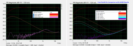
I did go ahead and give the LM385-2.5 modification a try just to see how its cross-talk performance would compare with using a completely separate reference voltage for the input opamp as was done in Post #1. Here is the circuit modification recommendations from the videos(screen captures) linked in Post #23. Basically, just replace R39 with the LM385-2.5 voltage reference(see attached datasheet) and increasing C13 value if needed.

The result is substantial improvement at low frequencies, but a slight hump of deterioration centered around 2kHz.
This would indicate an increase in output impedance of the voltage reference in this frequency range.
I tried increasing C13 to 1000uF, but it had no effect on the results.

So, not quite as good as the separate reference voltage, but certainly good enough for impedance measurements.
And as a bonus, you can retain the monitor switch functionality if that is important to you.