Davey,
Thnx for hint. I will try in near days with Audiotester software.
I had a problem with it and my soundcard under XP in 24/96 mode but in W2K it seems to work - so now I can make THD vs. freq measurements also hopefully 🙂
I plan to compare the "no analog stage" - passive only filtered output to my single opamp implementation.
To me it seems that even though the DAC is very capable to drive quite hard loads there is still limitations in there.
One of them seems to be when the signal is near full range (0dB), then the internal opamp is driven near rail to rail and the THD increases and also the sound is worse.
If you look at the performance with -3 or -5dB from full range it looks much better....
Ergo
Wow, this thread was a bit sleepy and it seems I have reanimated it for a while 🙂
Have fun !
Thierry
Have fun !
Thierry
mbroyles,
I think the transistor muting is there only to kill the switch on/off transient. This is the only condition when the DCX gives a transient with the analog stage taken out of the unit.
Ergo
I think the transistor muting is there only to kill the switch on/off transient. This is the only condition when the DCX gives a transient with the analog stage taken out of the unit.
Ergo
Hi Kuei,
re post510;-
Thmartin's modified output is single ended (unbalanced).
The fig2.4 circuit provides both unbalanced output and balanced source impedances from a single ended source. It even blocks DC which according to Davey is also needed.
In my view, this is not the opposite to what is required.
It seems to give dual output options from the passive filter in lieu of the DCX multi opamp stage.
Konnichiwa,
Actually the DAC has a BALANCED output. Why ON EARTH do you want to use it unbalanced and THEN to make a pretend balanced output from that, if you have a REAL balanced source?
What is needed is a series resistor/inductor (to taste) , shunt capacitor to ground and coupling capacitor PER PHASE connectiong to the XLR pin 2 & 3 with pin 1 to ground and DC leakage resistors from pin 2 & 3 to ground.
An unbalanced output is then connected between pin 1 (ring) and 2 (tip) if required. The circuit you suggest is entierly INAPROPRIATE when a balanced source exists!
Sayonara
AndrewT said:Thmartin's modified output is single ended (unbalanced).
The fig2.4 circuit provides both unbalanced output and balanced source impedances from a single ended source. It even blocks DC which according to Davey is also needed.
In my view, this is not the opposite to what is required.
It seems to give dual output options from the passive filter in lieu of the DCX multi opamp stage.
Actually the DAC has a BALANCED output. Why ON EARTH do you want to use it unbalanced and THEN to make a pretend balanced output from that, if you have a REAL balanced source?
What is needed is a series resistor/inductor (to taste) , shunt capacitor to ground and coupling capacitor PER PHASE connectiong to the XLR pin 2 & 3 with pin 1 to ground and DC leakage resistors from pin 2 & 3 to ground.
An unbalanced output is then connected between pin 1 (ring) and 2 (tip) if required. The circuit you suggest is entierly INAPROPRIATE when a balanced source exists!
Sayonara
ehhhmm, sorry to ask but has anybody tried the circuit op page 19 of the AKM-pdf? Lets say with silver-mica caps and opa2134
This may be a stupid question but it is a bit difficult to see what you guys did do and/or simulated with what results. Or maybe I missed/not understood something😕
This may be a stupid question but it is a bit difficult to see what you guys did do and/or simulated with what results. Or maybe I missed/not understood something😕
Question:How is the signal divaided (Sorry my English) from the dac´s
2 outputs to the six outputs?Is it trough the DSP or?
2 outputs to the six outputs?Is it trough the DSP or?
Ryssen,
There are actually 3 DAC's inside the DCX. DAC-1 handles Outputs 1 & 2, DAC-2 handles Outputs 3 & 4, etc.
Each DAC has two differential outputs and thus the six total available outputs. DSP allows the versatility in routing.
Cheers,
Davey.
There are actually 3 DAC's inside the DCX. DAC-1 handles Outputs 1 & 2, DAC-2 handles Outputs 3 & 4, etc.
Each DAC has two differential outputs and thus the six total available outputs. DSP allows the versatility in routing.
Cheers,
Davey.
Passive lowpass makes distortion
The low pass filter suggested by Thierry with the 33 Ohm and 100nF capacitor makes the output distort
Thierry´s measurement:
http://www.diyaudio.com/forums/showthread.php?postid=799929#post799929
and mine:
Left channel is with the filter above. Right channel is without any filter ( just a DC blocking capacitor)
And the big version here:
http://home19.inet.tele.dk/henckel/pic/IMD-big.png
Measurement conditions:
Digital in DCX - analog out of DCX and directly into Teratec DMX 24/96 soundcard - showing RMAA´s intermodulation distortion
Samplerate: 44,1 Khz/ 24 bit
This clearly shows that the Op amp in the DAC´s are overloaded. Calculating gives a Z value at approx 70 ohms at 30 KHz.
So what i suggets that we scale this passive low pass filter to values of 330 Ohm and 10 nF.
Any views on this ?
The low pass filter suggested by Thierry with the 33 Ohm and 100nF capacitor makes the output distort
Thierry´s measurement:
http://www.diyaudio.com/forums/showthread.php?postid=799929#post799929
and mine:
Left channel is with the filter above. Right channel is without any filter ( just a DC blocking capacitor)
An externally hosted image should be here but it was not working when we last tested it.
And the big version here:
http://home19.inet.tele.dk/henckel/pic/IMD-big.png
Measurement conditions:
Digital in DCX - analog out of DCX and directly into Teratec DMX 24/96 soundcard - showing RMAA´s intermodulation distortion
Samplerate: 44,1 Khz/ 24 bit
This clearly shows that the Op amp in the DAC´s are overloaded. Calculating gives a Z value at approx 70 ohms at 30 KHz.
So what i suggets that we scale this passive low pass filter to values of 330 Ohm and 10 nF.
Any views on this ?
Hi Henckel,
Very interesting, thanks for that.
There's no doubt that distortion is present as the two graphs show.
Could you please have a try with 1KR and 3,3nF as I have no more access to any measurement equipment for a while 🙁
Thanks
Thierry
Very interesting, thanks for that.
There's no doubt that distortion is present as the two graphs show.
Could you please have a try with 1KR and 3,3nF as I have no more access to any measurement equipment for a while 🙁
Thanks
Thierry
Thmartin said:Hi Henckel,
Could you please have a try with 1KR and 3,3nF as I have no more access to any measurement equipment for a while 🙁
Thanks
Thierry
So i haver tried 1,5 Kohm and 100 nF ( i dont have anything smaller than 100nF) available today ;-)
An externally hosted image should be here but it was not working when we last tested it.
and the big one:
http://home19.inet.tele.dk/henckel/pic/IMD-big-1500+100nF.png
It still shows a increase in distortion - so it seems that the limit of 2KOhm loading of the output of the DAC must be respected. - This leaves either the option to:
1) No filter at all (Just a DC-blocking capacitor)
2) A choke in series with the output ( type and supplier ?)
3) The single opamp config shown in the Datasheet of the DAC ( this also have the benefit of getting rid of the DC-blocking capacitor and actually making use of the ballanced output of the DAC)
Henckel,
I'm wondering about the RMAA analyzer program. What type of excitation is used for the IM distortion testing? That looks like some sort of a noise-based testing scenario. I've been doing some distortion/amplitude testing directly on the DAC outputs with a few different RC filters and SpectraPlus and my results are much better (or at least appear to be) than this. I will post some screenshots ASAP.
The output filter circuit shown in Figure 11. of the 4393 data sheet is essentially the same thing as the filter stage used by Behringer, (but without the following coupling capacitor.)
Also of note is the "Example 2" (recommended) output circuit shown on page 20 of the datasheet loads the DAC outputs with 620 ohms.
Cheers,
Davey.
Davey said:Henckel,
I'm wondering about the RMAA analyzer program. What type of excitation is used for the IM distortion testing? That looks like some sort of a noise-based testing scenario. I've been doing some distortion/amplitude testing directly on the DAC outputs with a few different RC filters and SpectraPlus and my results are much better (or at least appear to be) than this. I will post some screenshots ASAP.
The output filter circuit shown in Figure 11. of the 4393 data sheet is essentially the same thing as the filter stage used by Behringer, (but without the following coupling capacitor.)
Also of note is the "Example 2" (recommended) output circuit shown on page 20 of the datasheet loads the DAC outputs with 620 ohms.
Cheers,
Davey.
The measurement methode is:
A new test of intermodulation distortion has been added. From RMAA 5.1 the common IMD test uses a standard SMPTE test signal. In a new Swept sine IMD test, we use a set of 2 harmonics with a frequency difference of 1 kHz (CCIF standard), sweeping the whole audible range of frequencies. Thus, the dependence of intermodulation from frequency is tested. This test allows detecting high-frequency intermodulations that are specific to internal sample rate convertion (SRC) algorithms of a sound card.
From this page: http://audio.rightmark.org/index_new.shtml
Singel tone THD measurement will surely give better results - at least because the harmonicsof say 10 KHz will be outside the audible band ?(sampling frequences 44,1 Khz?)
On the output - yes the first stage of the behringer is in reality the same as i was proposing - might be worth a try
By all means let se some more measurements also of interest would be the noise of the DCX as mine have some very distinct spikes in the 2-6 Khz area and also some from 200-700 Hz
t still shows a increase in distortion - so it seems that the limit of 2KOhm loading of the output of the DAC must be respected. - This leaves either the option to:
1) No filter at all (Just a DC-blocking capacitor)
Thats what I said.😀 😀 😀
My Dcx2496 mods compared and compiled from The Yahoogroup
I have tried many different circuits to improve the sound of the 2496 Behringers. They all use the excellent AKM AK4393 dac chip which is unique in having a true balanced VOLTAGE output with enough power to drive through a passive stepped attenuator direct to the power amp. This direct out, capacitor coupled with film and foil caps, first order analog low pass filter, gives an incredible see through sound with the blackest of background. after trying many different output schemes I have settled on this one for it's sound quality and simplicity. All my evaluations were done on my DCX2496 which has a ribbon cable that allows access to the output of the dacs. During the course of my evaluations I have tried the following:
1. Bypassing the 47uf electrolytic interstage coupling cap with a .1uf Dayton film and foil cap. This simple mod made a nice improvement.
2. Behringer runs a crazy servo shifting balanced output stage. Because I'm running my amps single ended right now, I took the signal out before these stages for another small improvement.
3. I implimented a custom analog output board with LT1360 opamps running as a differential amp and lots of bypassed filter caps. This was a huge improvement and nearly equaled the direct out scheme for sound but is obviously more expensive and complicated.
4. I tried multi-tapped Sowter transformers. These were easy to install, gave me volume control inside the unit and had an beautiful, liquid sound but were a bit euphonic and didn't match the fine resolution of the direct output. And they were obviously much more expensive.
I have some .01uf Dayton foil caps so I can try so I can try easing the load through the filter with 360 ohms but interestingly, the sound is better with the first order filter running through 36 ohms than with no filter.
Op-Amp output
You should also look at M-Audio SuperDAC output stage, (same DAC chip).
Sounds great, and is very similar to the DAC-appnote.
(schematics are found on http://groups.yahoo.com/group/M-Audio_SuperDAC_2496/
Arne K
You should also look at M-Audio SuperDAC output stage, (same DAC chip).
Sounds great, and is very similar to the DAC-appnote.
(schematics are found on http://groups.yahoo.com/group/M-Audio_SuperDAC_2496/
Arne K
Hi all,
It's interesting to see that's everybody is talking about modyfing the output stage (DAC, Analog output) and not a single word about the input. At least i did not see any.
Does the ADC stage accept also balance inputs?
If not, (most likely) there is probably a balance driver (an op-amp that converts balance to single ended) in the input, and if we accept the ''less is better'' principle and we don't need balance input these can also be removed. Right?
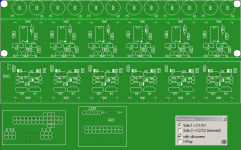
Does anyone have the schematic diagram of the DCX or know where can I find it?
Happy new year.
Padel
It's interesting to see that's everybody is talking about modyfing the output stage (DAC, Analog output) and not a single word about the input. At least i did not see any.
Does the ADC stage accept also balance inputs?
If not, (most likely) there is probably a balance driver (an op-amp that converts balance to single ended) in the input, and if we accept the ''less is better'' principle and we don't need balance input these can also be removed. Right?
Does anyone have the schematic diagram of the DCX or know where can I find it?
Happy new year.
Padel
Another analog filter repost from Yahoogroups/DCX
I actually ran mine with the dacs running straight out with no output R
or filter but prefer the first order analog filter at around 40k. It
makes the sound more liquid, fleshed out and musical. I listened to
many different filters, first and second order from 20k(obviously way
too low) to 160k and like the 6db 40k filter the best. The beauty of
this mod is that it is easily reversible (just solder the ribbon cable
and output leads back together) and fine tuneable.
Search user name sendler at
http://groups.yahoo.com/group/DCX2496/
for numerous posts on the progression of my DCX mods.
- Home
- Source & Line
- Digital Line Level
- Behringer DCX2496 digital X-over