OK, that's a strange one....
I used to have some pop and drop issues when I was running 44.1K out of a laptop to the DCX. Found it was a grounding problem. Using a 75 ohm to 110 ohm transformer helped, as did better grounding. But I didn't relate that to the DCX, just to my bad wiring.
Simple fix - do you think it hurts to up-sample with your sound card? Since the DCX up-samples to 96/24 anyway. Do it in software, do it in the soundcard, do it in the DCX. Not sure which is best. That doesn't help you with the CD player, tho. 🙁
I wonder if a 75>100 ohm transformer would help?
I go for the 96 up-sample in the sound card. It works.
Unfortunately we don't have real grounded power in this house.
Unfortunately we don't have real grounded power in this house.
I think this confirms you have a "pin 1 Problem".
google it.
Build the hum detector that Whitlock/Rane suggests.
Pin 1 of all outputs and all inputs goes direct to Chassis at the in/out socket.
Never to the PCB, nor other grounds, inside the chassis.
I will check this! Thx
Pilgham Audio SRC - Where to connect V+?
Took my dismantled DCX off the shelf after years. I once bought a Pilgham Audio SRC/Clock but mislayed the manual and so I wonder where to connect V+ ...
Can someone provide a picture or simply tell me what pin ist to be fed with V+?
THX!
Took my dismantled DCX off the shelf after years. I once bought a Pilgham Audio SRC/Clock but mislayed the manual and so I wonder where to connect V+ ...
Can someone provide a picture or simply tell me what pin ist to be fed with V+?
THX!
Took my dismantled DCX off the shelf after years. I once bought a Pilgham Audio SRC/Clock but mislayed the manual and so I wonder where to connect V+ ...
Can someone provide a picture or simply tell me what pin ist to be fed with V+?
THX!
SRC/clock mod installation instructions
1. Disassemble R34 (22 ohm) on solder side of DSP board
3. Disassemble IC1 (CS8420) on component side of DSP board
Preferably with hot air or cut the pins carefully or lift the single pins with a needle and soldering iron
Avoid any forces on the PCB !
4. Assemble female 26-pin ERNI connector instead of IC1
a, "Straighten all pins of row B a little bit so that they touch the pads of CS8420
Flatten all pins of row A"
b, Solder row B: B1 = pin28 ... B13 = pin16
c, Bend (45°) long side of pins close (~1mm) to the header and cut pins on long side of pin header
d, "Insert pin header: A1=pin1 …. A10=pin10
underneath pins of SMD connector"
e, Insert wire: A3 = 9volt (IC7,pin1 or connectorX3,pin3)
Attachments

I wonder if this was a near permanent failure in my DCX? Even though I used analogue input.Modifications for Behringer DCX-2496
1. ‘Dull sound’ problem (digital input)
I could not get my active to sound as good as passive. That why I gave up that project.
Now I suppose I have to fit the "Oettle Mods" and steel my self up for trying again.
psu for dcx2496
hi everyone,
do any of you know where i can buy a new or used psu for a dcx2496?
cheers,
al
hi everyone,
do any of you know where i can buy a new or used psu for a dcx2496?
cheers,
al
hi everyone,
do any of you know where i can buy a new or used psu for a dcx2496?
cheers,
al
The SMPS of my DCX broke down too - it turned out to be one of those bad elco cases. The 400V 47uF directly behind the (high voltage!) rectifier to be precise. It showed a slightly bulged top. After all it was an inexpensive and easy fix, I would say check that elco first.
PSU question: if you don't use the analog sections, at all (no in, no out) and rely only on digital - do you need anything other than 5v on the main psu? can the main psu board be fully replaced with a linear 5v psu, on an all-digital modded dcx?
I'm thinking of doing an spdif-out board that works similar to my existing prototype. my proto has been working fine for over a year now and I'm thinking of doing a board layout for it (finally). while I'm doing that, I'm wondering if the main stock psu can be yanked out entirely and replaced with a simple 5v linear.
my spdif-out board uses wm8804 or 05 chips and I made this proto a year or two ago. I'm wondering if there are any newer spdif-transmitter chips out there that I should consider, or just keep using the wolfson (which does seem to work for me and is simple enough to get working).
The DCX2496's PSU output has 7 pins (A for analog, D for digital):
1. +15VA
2. -15VA
3. +9VA
4. AGND
5. DGND
6. +5VD
7. +3.3VD
The +/-15VA outputs are for the opamps, and the +9VA is further regulated down to 5V for other analog sections, including those on the ADC and DAC chips. This 5V is also voltage-divided to serve as a reference for a pass-transistor to output 3.3V for the analog section.
The +5VD and +3.3VD are used for various digital sections. So, in addition to the 5V, you need at least also the 3.3V.
EDIT: The +15VA is also used to power an opamp that translates PWM into a LCDVEE control voltage for LCD display brightness, so you can't skip that either...
Last edited:
I guess I did not remember the internal layout all that well: when I opened my unit, the rear analog-out board is the WHOLE rear unit, pretty much. db connector and the 3 xlr inputs, too. so I can't just easily remove that whole rear board like I was thinking I could. oh well.
I was able to remove it, unsolder all the xlr's on the analog outs and make room for my set of rear bnc connectors, for the spdif-out mod. the desoldering went very well and I now have lots of rear panel room. pics to follow when the wiring is cleaned up a bit more 😉
I was able to remove it, unsolder all the xlr's on the analog outs and make room for my set of rear bnc connectors, for the spdif-out mod. the desoldering went very well and I now have lots of rear panel room. pics to follow when the wiring is cleaned up a bit more 😉
here's a photo of my current dcx setup. I'm still using the wolfson spdif-out DIY board and I'm going into 2 AK4399 ebay dacs. those feed into the parasound multichannel amp, then onto 'zaph audio' L18 spkrs in fully active XO mode. the silver box with the lcd display is my cs3318 vol control 1U chassis and it is the middle-man between the AK dacs and the parasound amp.
next phase is to proto one AK spdif tx chip, get some experience with it and, hopefully, make a board that contains 3 of them.
next phase is to proto one AK spdif tx chip, get some experience with it and, hopefully, make a board that contains 3 of them.
Attachments
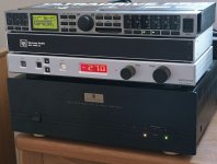
here's a photo of my current dcx setup. I'm still using the wolfson spdif-out DIY board and I'm going into 2 AK4399 ebay dacs. those feed into the parasound multichannel amp, then onto 'zaph audio' L18 spkrs in fully active XO mode. the silver box with the lcd display is my cs3318 vol control 1U chassis and it is the middle-man between the AK dacs and the parasound amp.
next phase is to proto one AK spdif tx chip, get some experience with it and, hopefully, make a board that contains 3 of them.
Nice setup man! 😀
Hi guys. I am a newbie when it comes to active xovers. Can i use the dcx with a Nad M51 dac bypassing the dcx dacs' so i can play 24/192 files. Thx.
Hi guys. I am a newbie when it comes to active xovers. Can i use the dcx with a Nad M51 dac bypassing the dcx dacs' so i can play 24/192 files. Thx.
No it is limited to 96k. Check out the Najda WAF-Audio It is a main board only so is a bit DIY but will do what you want.
Last edited:
you could replace the SRC chip in the dcx (a bit of effort for that); or you could samplerate convert outside the box via software or hardware. SRC down to 96k before sending to the dcx. not really a big deal, although purists will always complain 😉
Guys, I need some help please. I burnt the paths on 2 out of 3 channels trying to swap the caps C6-C11 next to X1 ribbon cable socket.
There is no DCX datasheet to my knowledge and on my version of pcb I can't see how these caps are connected to DAC chips. Does anyone know (or see) how to wire these caps?
There is no DCX datasheet to my knowledge and on my version of pcb I can't see how these caps are connected to DAC chips. Does anyone know (or see) how to wire these caps?
- Home
- Source & Line
- Digital Line Level
- Behringer DCX2496 digital X-over