While measuring stuff I noticed the input VAC looks clipped? I didn't see this before while dealing with power transformers.
Is this normal?
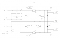
The transformer seems to have a 37VAC rms secondary center tapped for two 18.5VAC rms output. I see written on the transformer that secondaries are at 18.3VAC / 0.4A so that makes sense.
The whole unit draws about 35mA /230VAC. Works at about 8W total power consumption. Or about 100mA per rail with only two LEDs lit up.
For some reason the top side of the LEDs don't light up, the ones indicating input/output signal presence. Must check the daughter board.
100mA per rail from 400mA that the transformer can deliver seems pretty decent. Doesn't seem that there's something wrong with the power supply.
I just don't understand how come the signal is clipped.
Is this normal?
The transformer seems to have a 37VAC rms secondary center tapped for two 18.5VAC rms output. I see written on the transformer that secondaries are at 18.3VAC / 0.4A so that makes sense.
The whole unit draws about 35mA /230VAC. Works at about 8W total power consumption. Or about 100mA per rail with only two LEDs lit up.
For some reason the top side of the LEDs don't light up, the ones indicating input/output signal presence. Must check the daughter board.
100mA per rail from 400mA that the transformer can deliver seems pretty decent. Doesn't seem that there's something wrong with the power supply.
I just don't understand how come the signal is clipped.
Attachments
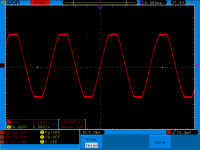
It seems my mains voltage is actually crap, and flat topped.
Will have a talk with the provider.
Will have a talk with the provider.
For starters because this is a 1995 unit. That's 20 years.
The unit has Samxon GR series capacitors (it's the same as CapXon GR). These are general purpose 85 degrees C rated for 2000 hours. Given a conservative of 5 hours a week it works out at almost 5000 hours, so they are a good bit over their lifetime rating.
It doesn't quite work like that 🙂 Its 2000 hrs at their maximum ratings, and that includes running at max ripple current.
Its a bit like a filament bulb... for example
1000 hours @ 12 volt
2000 hours @ 11 volt
4000 hours @10.5 volts
8000 hours @ 9.5 volts
16000 hours @ 8 volts
32000 hours @ 6 volts
Get the idea.
One other technical thing that I'd like to know if anyone is willing to help.
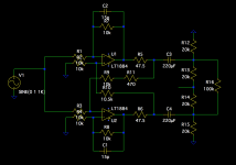
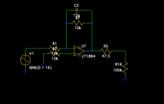
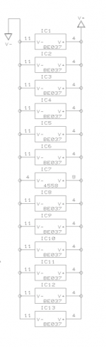
Since I don't have a balanced input into my amp I was thinking of removing some components from the circuit. The adapter cables I use put one line at ground, therefore rendering one output op amp useless (as I see it).
Also the symmetry adjustments serve no purpose at this point.
Can I adjust the output circuit like this? I attached before/after of the circuit.
Attachments
It doesn't quite work like that 🙂 Its 2000 hrs at their maximum ratings, and that includes running at max ripple current.
Its a bit like a filament bulb... for example
1000 hours @ 12 volt
2000 hours @ 11 volt
4000 hours @10.5 volts
8000 hours @ 9.5 volts
16000 hours @ 8 volts
32000 hours @ 6 volts
Get the idea.
I understand that, and theoretically that's ok. But in my context it is a risk.
Just thinking of racks with high power amplifiers can easily raise the temp in the case.
For a hi-fi unit that's been run in a home I guess ok, you could think that.
But, anyway, having general purpose Samxon caps in my system just doesn't feel right. These units have been engineered to the lowest cost possible.
Let me show you again the unit that replaced mine from Behringer 🙂
It is the newer CX2310:
An externally hosted image should be here but it was not working when we last tested it.
I can see you are going to replace the caps anyway 😉
The unbalanced conversion looks OK, just make sure you retain the correct half to maintain overall non inversion phase from input to output.
The unbalanced conversion looks OK, just make sure you retain the correct half to maintain overall non inversion phase from input to output.
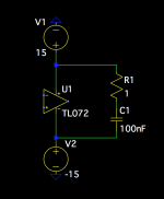
What would be best for these op-amps? To add decoupling from each rail to ground on each device or just a cap between the rails or both, a cap between the rails and a cap between each rail and ground?
I presume 100nF would do for any of these caps?
I presume 100nF would do for any of these caps?
I tend to favour rail to rail. A 100nf ceramic is ideal but I would perhaps include a series 1 ohm 0.25w carbon resistor to eliminate any possible ringing... which is highly unlikely tbh.
The 'blanket' will be noisy power supplies - so what Xoc1 said. Except instead of 100nF across the quad opamps' power pins I'd go all-out and fit a low ESR 'lytic there, at least 470uF on each.
470uF? Isn't that like many orders of magnitude higher than what is usually used? Like 100nF?
I tend to favour rail to rail. A 100nf ceramic is ideal but I would perhaps include a series 1 ohm 0.25w carbon resistor to eliminate any possible ringing... which is highly unlikely tbh.
You mean like this?
I'm making the order for parts tonight so I might as well do it right. But I don't like going overboard with values. Like 470uF, I don't understand why a value that large would be beneficial in that spot.
Attachments
Yes like that. There isn't always a right and wrong over issues like this, many have their own methods and solutions. There will already be decoupling on the PCB, probably small electros ? Adding the 0.1uf just clamps things down at HF where the electros start to lose effect due to their rising self inductance. The series resistor just tames any tendency for any voltage spikes on the rails causing ringing.
Yes like that. There isn't always a right and wrong over issues like this, many have their own methods and solutions. There will already be decoupling on the PCB, probably small electros ? Adding the 0.1uf just clamps things down at HF where the electros start to lose effect due to their rising self inductance. The series resistor just tames any tendency for any voltage spikes on the rails causing ringing.
You'd be surprised...
I found nothing on the pcb.
The only capacitors from the power supply are the two main ones behind the regulators, another two after the regulators on each rail, with ceramic 0.1uF bypassed and another 10uF between the rails.
To be hones the 10uF one is all the way where the first op amp is, probably because the traces go to the op amps from there.
Also the schematic shows only what I mentioned. So no bypass at op amp location.
Attachments
In that case I would add small electros directly under or on top of the chips soldered direct to the pins. Use either 4.7 or 10 uf, no larger and nothing exotic, just standard miniature electros. And keep the 0.1 scheme as well.
Ok Mooly, thank you once again for helping 🙂
I will come back after I've finished the job with pictures and feedback.
I will come back after I've finished the job with pictures and feedback.
Ah, forgot.
I will buy new op amps as they are cheap. 4$ for all 12 quad TL074.
I can't buy the more recommended lower noise higher slew rate ones as they are expensive and cost adds up.
But I could get 4 different ones for output or crossover duties if some would be more recommended than the TL074 ones.
Must be dual supply.
TL074 are JFET-Input.
The +85oC max is THE most important rating* Without high power ripple current or tropical conditions you are going nowhere near this. So your lifetime guesses are hopelessly pessimistic.
I know you will ignore this as you are again on an obsessive quest. Such is your right, of course, but I do find it annoying and detrimental to the art to re-enforce for others these myths about elcos (and op-amps!) without any real evidence.
* google it on the Illinois web site.
I know you will ignore this as you are again on an obsessive quest. Such is your right, of course, but I do find it annoying and detrimental to the art to re-enforce for others these myths about elcos (and op-amps!) without any real evidence.
* google it on the Illinois web site.
The +85oC max is THE most important rating* Without high power ripple current or tropical conditions you are going nowhere near this. So your lifetime guesses are hopelessly pessimistic.
I know you will ignore this as you are again on an obsessive quest. Such is your right, of course, but I do find it annoying and detrimental to the art to re-enforce for others these myths about elcos (and op-amps!) without any real evidence.
* google it on the Illinois web site.
So you are saying that it's not very likely that this device has been used in a hot environment?
It's a PA crossover.
I'm just looking to upgrade the unit. Why is it bad? Aren't we on DIY audio?
Op amps have no decoupling, the ps is crap, -14.5V on the negative rail.
General purpose electrolytic capacitors in the signal path.
Fuse has been bypassed with a wire kind of used&abused unit.
All this and you're still saying to keep it stock and listen to it like it is? 😕
In case it wasn't clear, my quest was to remove unnecessary components for hi-fi use at home.
And to replace electrolytic caps with film ones just to be safe in the future. If my circuit allows low enough values that I can switch from electrolytic to film then why is it bad?
The film ones are 60 cents a pop.
And to replace electrolytic caps with film ones just to be safe in the future. If my circuit allows low enough values that I can switch from electrolytic to film then why is it bad?
The film ones are 60 cents a pop.
It is not bad - you can do whatever you want to your own equipment.
However, when other people read this forum in the future, it would be better if they can rely on evidence based data which is not mixed in with woo.
From post 19,
"The unit has Samxon GR series capacitors (it's the same as CapXon GR). These are general purpose 85 degrees C rated for 2000 hours. ..."
This false information! That rating would scare anyone if true. That is 2000 hours (~ 12 weeks) at 85oC!
Anyway, enough from me .
- Status
- Not open for further replies.
- Home
- Source & Line
- Analog Line Level
- Behringer CX2300 replace caps (values change)