Ok, so readers are better off with what you are saying then? :
If anyone buys a second hand PA unit, abused, unit that's been manufactured in 1995, they shouldn't worry about the electrolytic capacitors in the signal path, general purpose Capxon 85 degrees C rated if they plan to use it at home in their Hi-Fi (ish) setup.
Ah, forgot.
I will buy new op amps as they are cheap. 4$ for all 12 quad TL074.
I can't buy the more recommended lower noise higher slew rate ones as they are expensive and cost adds up.
But I could get 4 different ones for output or crossover duties if some would be more recommended than the TL074 ones.
Must be dual supply.
TL074 are JFET-Input.
TLO74's are good performers. No point replacing them like for like just for the sake of it.
Also if you have 12 of them then the power supply requirements add up. What is a single opamps current draw (TLO71) ? Around 3ma. That's 48 times 3ma, 144ma total. Imagine replacing those with something that drew significantly more.
TLE2074 Excaliber devices could be one possible substitute. Direct replacement and improved version of the original TLO series.
470uF? Isn't that like many orders of magnitude higher than what is usually used? Like 100nF?
Yep, right it is. But then the SQ usually encountered with opamps sucks - as we've both noticed. Lower impedance on the rails is what I've found improves dynamics.
If you have a lot of time and patience but very little funds you could improve the SQ by scaling up the impedances wherever possible. So for example in the input HPF where there're 470nF caps, you could go down to 47nF and increase the resistors by a factor of 10. But its a fair amount of work to do this throughout the whole unit - however it'll pay dividends in SQ by reducing the dynamic current draw. TL074s sound great when they're really lightly loaded and because they're FET input they can work with resistors in the 100k - 1Mohm range without offset and noise problems.
Once the supplies for the op amps are sorted you could look at upgrading the rest of the circuit and linking out features that you don't need.
But how accurate are you expecting the filters to be when they rely on ganged potentiometers?
But how accurate are you expecting the filters to be when they rely on ganged potentiometers?
TLE2074 Excaliber devices could be one possible substitute. Direct replacement and improved version of the original TLO series.
I found them from my supplier but price of one is as much as all tl074 cost 🙂
But I will keep them in mind for future maybe.
If you have a lot of time and patience but very little funds you could improve the SQ by scaling up the impedances wherever possible. So for example in the input HPF where there're 470nF caps, you could go down to 47nF and increase the resistors by a factor of 10. But its a fair amount of work to do this throughout the whole unit - however it'll pay dividends in SQ by reducing the dynamic current draw. TL074s sound great when they're really lightly loaded and because they're FET input they can work with resistors in the 100k - 1Mohm range without offset and noise problems.
I made a simulation with your recommended values and the frequency response looks the same. Then I simulated it with resistor values that I could easily source and the differences are barely noticeable while looking very careful at both responses side by side, practically identical.
This seems like a good thing to try, resistors are cheap, and there's a total of 8 resistors that need changing. The capacitors were being replaced anyway with Wima ones.
Once the supplies for the op amps are sorted you could look at upgrading the rest of the circuit and linking out features that you don't need.
But how accurate are you expecting the filters to be when they rely on ganged potentiometers?
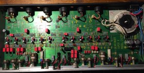
I already took out the limiter circuits and the CD EQ function that I won't need, also the balanced output.
Theoretically the xover point of this unit would be fixed for long in the future as I'm going to be using it with my Diamond speakers (bi-amped).
I made a test in it's current state and the knob doesn't represent at all the xover frequency. It's at least 2-3KHz out.
Of course I will set the xover point using the oscilloscope. I don't trust that knob at all 🙂
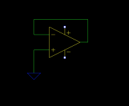
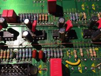
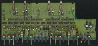
The quad op amps in this unit are not fully used. There are packages with unused sections. Taking out the balanced output leaves only 2 out of the 4 op amps in the quad package working. I might as well use a double package one but I'd have to make an adapter and use a smd double op amp package so I can link the correct pins. But maybe for another time.
Right now I want to get the quality up a bit with small investment.
These are DC blocking capacitors. A properly configured DC blocking cap should have virtually no effect on the signal, since its impedance will be (should be) very low compared to the other impedances (resistors etc) in the circuit. It is my opinion that swapping these caps will at best provide a very marginal improvement, assuming they're not defective of course.
What I have seen in consumer grade equipment is small value non-polarized electrolytic capacitors used in a filter for equalization. In this application the impedance of the capacitor is being exploited and is significant, and replacing them should make a small but worthwhile improvement. These capacitors are typically found in the lowest frequency adjustment in graphic equalizers, in values of around 0.47 uF to maybe 4.7 uF. If you can find a better capacitor that fits the board, then it's worthwhile.
What I have seen in consumer grade equipment is small value non-polarized electrolytic capacitors used in a filter for equalization. In this application the impedance of the capacitor is being exploited and is significant, and replacing them should make a small but worthwhile improvement. These capacitors are typically found in the lowest frequency adjustment in graphic equalizers, in values of around 0.47 uF to maybe 4.7 uF. If you can find a better capacitor that fits the board, then it's worthwhile.
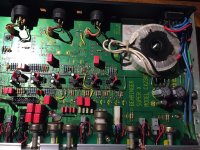
I just started replacing the parts and I noticed that there is a difference between the schematic and the PCB.
On the schematic there is a 47nF cap between the earth and ground. On the pcb that capacitor is missing, only a wire link instead.
Should I install the cap?
Also is that value critical? I think I have 100nF available on that footprint.
On the schematic there is a 47nF cap between the earth and ground. On the pcb that capacitor is missing, only a wire link instead.
Should I install the cap?
Also is that value critical? I think I have 100nF available on that footprint.
Attachments
Leave it as designed. That kind of thing is absolutely typical of commercial stuff, they cover all bases in the PCB layout so if a problem shows such as a buzz or noise or susceptibility to RF then they have other options already built into the layout to hopefully overcome the issue.
I finished the job and it turned out great! 🙂
I'm really happy as there's no blanket over the speakers anymore.
Right now I feel that the unit is fully transparent to my ears.
I really like how my system sounds with this setup.
I matched the crossover points with the oscilloscope and now I'm fully bi-amped
The freq pot is off by about 500Hz but I really don't care. I should glue it in place in case someone fiddles with the knobs....
I kept the muting function but didn't keep the limiter and clipping functions.
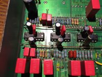
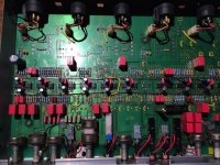
I had no elegant way of connecting the extra capacitors so I just installed some ground wires that go back near the main caps. They seem to be pretty solid after soldering, they are kept mid-air by the caps themselves.
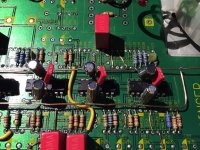
Also I removed extra components so I could properly terminate the op-amps that are not used anymore. I attached the way I did it for all of them. Some links here and there.
I haven't found the time to do measurements for freq response but hope I will. So far it sounds great!
Maybe I will do some more improvements in the future but I'm not sure at the moment. Maybe a cheap R-Core transformer from ebay, and a LM317/LM337 supply mod but I'm not sure if it's worth the hassle. Also I'm not sure if further on I could hear any improvements. So far the unit is transparent for me.
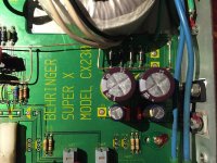
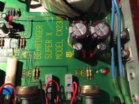
The main caps are Nichicon PW 1800uF/35V. They were the ones that I could source and they are low esr. The rest of the electrolytic caps are Panasonic FC. The ones after the regulators are 470uF/25V, the one that sits between the rails is 220uF/50V, and the small ones on each op-amp are 10uF/50V.
I've replaced the regulators and I did find a plastic encapsulated negative one. The diodes are UF4004. The PS caps match the footprint.
I'm really happy as there's no blanket over the speakers anymore.
Right now I feel that the unit is fully transparent to my ears.
I really like how my system sounds with this setup.
I matched the crossover points with the oscilloscope and now I'm fully bi-amped
The freq pot is off by about 500Hz but I really don't care. I should glue it in place in case someone fiddles with the knobs....
I kept the muting function but didn't keep the limiter and clipping functions.
I had no elegant way of connecting the extra capacitors so I just installed some ground wires that go back near the main caps. They seem to be pretty solid after soldering, they are kept mid-air by the caps themselves.
Also I removed extra components so I could properly terminate the op-amps that are not used anymore. I attached the way I did it for all of them. Some links here and there.
I haven't found the time to do measurements for freq response but hope I will. So far it sounds great!
Maybe I will do some more improvements in the future but I'm not sure at the moment. Maybe a cheap R-Core transformer from ebay, and a LM317/LM337 supply mod but I'm not sure if it's worth the hassle. Also I'm not sure if further on I could hear any improvements. So far the unit is transparent for me.
The main caps are Nichicon PW 1800uF/35V. They were the ones that I could source and they are low esr. The rest of the electrolytic caps are Panasonic FC. The ones after the regulators are 470uF/25V, the one that sits between the rails is 220uF/50V, and the small ones on each op-amp are 10uF/50V.
I've replaced the regulators and I did find a plastic encapsulated negative one. The diodes are UF4004. The PS caps match the footprint.
Attachments
-
 final schematic.png271.9 KB · Views: 170
 -
 terminated.png23.6 KB · Views: 164
 -
 IMG_2877.JPG274.7 KB · Views: 173
 -
 IMG_2876.JPG284.8 KB · Views: 162
 -
 IMG_2875.JPG444.4 KB · Views: 182
 -
 IMG_2874.JPG386.5 KB · Views: 194
 -
 IMG_2873.JPG444.2 KB · Views: 389
 -
 IMG_2872.JPG432.8 KB · Views: 230
 -
 IMG_2871.JPG436.2 KB · Views: 256
 -
 IMG_2869.JPG214.7 KB · Views: 286
Last edited:

Wow, you've put a lot of work into that. I like the power busses 🙂 What you have done with the opamps is correct.
That's great stuff - I really like taking mediocre grade equipment and making it into something satisfying.
Thanks!
The biggest pain was the massive ground plane with the small component pads. Couldn't get enough thermal mass on them and grounded parts were a pain to remove/replace. Other than that it went pretty smooth and worked from the first power up.
The biggest pain was the massive ground plane with the small component pads. Couldn't get enough thermal mass on them and grounded parts were a pain to remove/replace. Other than that it went pretty smooth and worked from the first power up.
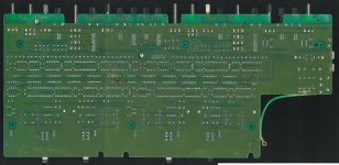
Do you have a high quality before picture of your crossover? I'm thinking about buying one and upgrading it, but would like to be able to see where to make the changes.
I don't know if and where they are, but I found someone else's pictures.
Rather than looking at the pictures with the replaced components I suggest you try and understand what and why has been replaced.
Follow the schematic and ask for help if you don't understand something.
I've also eliminated some options from this unit to suit my needs and it may not help you at all.
For example there's no limiter anymore, and phase swap doesn't work as well.
Also I think I've removed the mono-three way output as well but I'm not sure.
I suggest in the beginning to just sort out the power supply (caps, regs).
Attachments
I looking for an relatively inexpensive way to set up a crossover for some speaker designs I am experimenting with. It seems like your changes are exactly what I'm looking for... unbalanced input and output, don't care about 3 way mono operation, don't need a limiter.
There is one of these crossovers on craigslist locally for $40 but if it sounds like a blanket was placed on the speakers, it wouldn't be any use to me.
Do you have an updated schematic I can follow?
There is one of these crossovers on craigslist locally for $40 but if it sounds like a blanket was placed on the speakers, it wouldn't be any use to me.
Do you have an updated schematic I can follow?
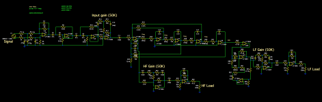
If you look a bit up at my post on the 22nd of April you will see the final schematic. I didn't bother to map the component names but with the original schematic and my final schematic you should be able to tell what's what on the pcb.
Don't worry on that unit, they are not that rare. Stay away from the newer cx2310, they are empty lunchboxes
Don't worry on that unit, they are not that rare. Stay away from the newer cx2310, they are empty lunchboxes
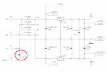
Curious Level Control Topology with two Electrolytics (polarized Caps)
First thank you for uploading the schematics in post #1
I have purchase this model in used condition for the aim to remove the passive components in the low frequency rail of Infinity Kappa 8.1.
I want to carried out some steps for enhancing sonic quality (please note: for home audio and no public address application).
When looking at the circuit I immediately notice the following things that are produce not good sound:
1) Parts arround IC1B - (first PDF in post #1, input unit, input Gain) I would change the following
- R125 by a variable resistor 10K-22K
- remove of R126, VR9, C62 and C63
Are there really a benefit by use of this topology ?
2) basically the same arround IC5B/IC3C (HF/LF Gain)
3) behind PIN8, IC5C/IC3C (HF/LF output) use of only an ordinary unity gain stage without mute- and limiter function and without output transformer for use in bal. mode
Maybe one of the members know additional steps for enhancing sound quality - thank you very much for further hints.
- Status
- Not open for further replies.
- Home
- Source & Line
- Analog Line Level
- Behringer CX2300 replace caps (values change)