After working for about 30 min one of the channels starts muffling and then dies off completely. I thought it has something to do with heating but oddly enough turning the amp off even for 10 sec fixes the problem (but only for another 2-3 min). Can heat sinks cool down that fast? The amp is barely warm on touch.
Another problem (related or not?) is that when turning the amp off the sound in the healthy channel persists for some time but the sick channel just makes a few "coughs" instead.
Any thoughts would be greatly appreciated.
Another problem (related or not?) is that when turning the amp off the sound in the healthy channel persists for some time but the sick channel just makes a few "coughs" instead.
Any thoughts would be greatly appreciated.
 I will clean up and relocate this to the solid state forum.
Any takers? Is it a bad cap or a transistor? The problem has worsen now as the "sick" channel sounds normal now only for 15min.
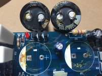
Generally the electrolyte is of that colour, but do the capacitor look swollen?
This is how leaked caps look like
This is how leaked caps look like
An externally hosted image should be here but it was not working when we last tested it.
+1Looks to me more like they were factory glued to the PCB.
That's my guess, too.
Caps can still be bad without spilling their insides, though.🙁
To follow up on this. Replacing the caps did not fix the problem. That residue on the board does appear to be some glue.
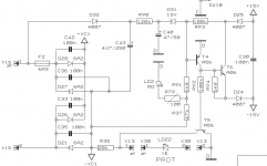
On further testing I have seem to localize the problem to the power module (?). It's schematic is given on the picture below. Connectors X16 go to the toroidal transformer.
The measured voltage across two diodes D25 and D24 is not 30V (as it is on a healthy channel) but is around 22V when the amp is turned on and then slowly drops to 11V or so.
Since I would like to avoid replacing every element in this thing, any ideas on what could be bad inside this module?
Attachments
Hello,
are you sure that it is the power supply? If the amplifier has failed components that are shorted or parasitic, it could be causing this voltage drop you are seeing.
unless you isolated the psu from the amp itself? if so i would check for failed capacitors with a capacitance check, there could be a cap intermittently shorting when it fills above a threshold which would cause a voltage drop. (and would discharge when you turn the amp off, essentially resetting itself.)
If you had not isolated the psu i would suggest doing so if possible.
are you sure that it is the power supply?
Thanks for following on this. No, I'm not sure. For the isolation, would it be enough to take out diodes D25, D26 and measure the voltage across transistor T6?
Hello,
you could try that, i would suggest isolation by somehow removing the +15 and -15v feeders from the load, and leaving the diodes in. Since i dont know how the circuit will act without the diodes (probably no difference with them in or out, but just to be sure)
judging from the schematic: the psu unit feeds its load with the +15 and -15v outputs (the ones coupled to C30) which these "15" values are in refrence to a ground (the ground seems to be the -VC1) So what you could do after you isolate the psu is measure the -15 to ground (dmm lead one on ground and dmm lead 2 on -15) and the same on the positive 15 side (reference it to ground) this would give you more insight into which side has a failure (pos side or neg side) IF the psu is to blame.
E.G. if -15 to ground measures fine (-15v DC) and +15 to ground measures fine but then dips. you know there's an issue with components that are on the +15 side.
Another way to test would be to check the amperage flowing out of the rails.
(just a note, regardless of the polarity of the rail you are testing, the black dmm lead goes on ground all the time. Even if the rail is -15v. Because with the black lead on the ground then your voltage should be negative, this is ok)
If the psu is fine, it seems like theres something awry in the components downstream of the psu. (obviously, i dont really need to tell you that) but does the amp show any other symptoms?
Thanks
After working for about 30 min one of the channels starts muffling and then dies off completely. I thought it has something to do with heating but oddly enough turning the amp off even for 10 sec fixes the problem (but only for another 2-3 min). Can heat sinks cool down that fast? The amp is barely warm on touch.
Another problem (related or not?) is that when turning the amp off the sound in the healthy channel persists for some time but the sick channel just makes a few "coughs" instead.
Any thoughts would be greatly appreciated.
This is indeed weird, but not unusual. We have put three of these into schools and in every case we have this problem. Behringer claim to have never heard of this problem, but it's obvious from here and other places that this is a design/manufacture problem. Very questionable ethics from Behringer regarding this. 😡 One unit went back to them for repair under warranty. They said no fault found and wanted to charge for this. We kicked up a stink and magically, they found a fault and sent it back. They wouldn't say what the fault was. It's now failed again. We are faced with throwing these 3 one year old amps in the garbage.
Is there any cure for the intermittent muffling and death of a channel? The system generally pops back into life if the input connector panel is flexed/massaged. We are not audio experts, but can follow some straight forward instructions.
The schematic looks a hit strange, but it's only a small part.I guess you should check/replace C40.Good luck.
Mona
Mona
First the whole schematic.
Here you see that there is a separate +/- 15V supply circuit.
Measure the voltages before and after R40 and R41.
Calculate the current flowing through these resistors.
I do believe that Behringer made an error in writing that the supply is 17V. Either 15 or 17V. Not that it matters a lot; as long as they are there.
I never had an A500 in repair but let's see if the power supplies are OK.
Next step is to isolate the problem.
My first guess is either a bad zener diode or the following cap (eg. D34 en C64 and/or D33 and C63)
Attachments
- Status
- Not open for further replies.
- Home
- Live Sound
- Instruments and Amps
- Behringer A500 power amplifier - weird problem