don't know what kind of glue this might be but i can guarantee that is extremely hard to remove form transistors. As about the heat transfer abilities of the specific chemical i also don't have any idea
The glue on the output transistors is hard, hopefully a thermally conductive cement used for adding heatsinks to computer ICs. I wouldn't even try to get it off the transistors, just replace them.
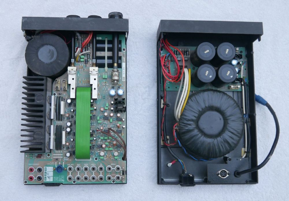
The transformers, rectifiers, PSU caps and standoffs are fixed with a contact adhesive, that is strong enough to enable the whole amp to be lifted holding just the transformer( best not do this.) I like this idea, save having PCBs wheer point to point is easy and is easier than drilling metal.
The top panel is fixed with a rubber based glue that is fine for normal use but weak enough to pry open if necessary, a bit of heat might help.
Turbo 225
Hello east electronics,
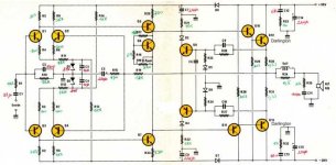
Here is the schematic of one amplifier 2x25W...the power stage use BDV65B & BDV64B...and as you tell a Vbe multiplier for thermal stability.
It's a very good amplfier ! I use it since 30 years without problem !
Best regards
Hello east electronics,
Here is the schematic of one amplifier 2x25W...the power stage use BDV65B & BDV64B...and as you tell a Vbe multiplier for thermal stability.
It's a very good amplfier ! I use it since 30 years without problem !
Best regards
Attachments
The amps have changed along with the cases, and the layout and wiring is neater now I believe. Tying the wires up with cable-ties is a no-no and the thermal cement for the output stage is designed specifically for the job and bloomin' expensive! The transistors aren't the same now either it seems.. Casework is now Perspex and heat-sinks are 5mm..
Here's a current AP10P

Here's a current AP10P
Last edited:
this one is a Vintage NVA40, quite a different case and heatsink...
worth checking?
worth checking?
An externally hosted image should be here but it was not working when we last tested it.
An externally hosted image should be here but it was not working when we last tested it.
An externally hosted image should be here but it was not working when we last tested it.
That NVA40 also has quite different wiring and layout to both early and 2014 versions of AP10P. Whatever you think of NVA design philosophy and assembly methods, this isn't the way to lay out a power supply for low noise.
Thanks Ian... I’m more concerned in personal safety and loudspeaker protection... this one doesn’t have any CE label.
I think NVA have only in recent years complied with product safety regulations and marked products accordingly. They don't even sell through retailers, as I understand from other posts here.
I'd assume its not the original wiring inside either. A lot of people now tinker with audio products and not all of them have any idea or respect for electrical safety, especially when converting products from foreign countries. If your mains power is floating (schuko plug type) your chassis may be unsafe without a ground wire and suitably grounded power socket. The NVA amps would not be approved for double insulated (2 wire) power so you would have good reasons for concern in most cases.
I'm not qualified to advise you on mains wiring but I would definitely seek out a local service technician who is familiar with the requirements for appliances like power amplifiers.
Loudspeaker protection is included in the form of current limiting and it is tuned to each model, by the look of the circuit. Naim and a few other UK manufacturers avoid relays this way and it does have advantages over relays which are forever screwing up the sound.
Hi and sorry to resurrect this old thread just for a question
I have one AP10 myself not used at present. I like the sound actually but also found it a little lacking in power.
I am not an expert but i understand rightly that there are some safety issues with this amp (i.e. not compliant with CE regulations)?
Would using an external and higher VA mains transformer with an umbilical cord going to the AP10 chassis solve some issues ?
That would have also the side effect to free some space inside the unit for placing bigger caps ... silly idea ?
Thanks a lot.
Last edited:
That would be a terrible idea. If you are going to take the transformer out then take the caps with it. Reservoir caps give the impression of just gently absorbing electrons in their own good time, but that's far from the case. They only charge at the top (or bottom) of the cycle and they present a near short. Huge currents pass in a very short time once the rectifier switches on, so the path from the bridge to the caps (and from the transformer to the bridge) should be as short as possible so as not to spray EMI all over your circuitry. Getting all these components out of the box is always a jolly good idea. Nor am I being hyperbolic here; a well known British manufacturer thinks it's a good idea to have the caps closer to the circuitry (because they know nothing about electronics though think they know everything) and have 2.5mm cable stretching the diagonal of their amplifiers. In the Stereophile review of this disaster 120 c/s (American model) spikes showed up on the output with no signal - which means they didn't bother to measure it either and probably still don't know why that was happening.
If you want a touch more power without bastardising the design, then take all this gubbins out and add another bridge rectifier (or set of diodes if they are not using a KBPC35 or similar) and add two more reservoir caps of the same make, model and value. This will allow you to power each channel separately and your supplies will droop by about half as much under load. (I don't know this amp but I'm assuming these supplies aren't regulated. If they are then you have a bigger task on your hands.
Personally I wouldn't change the value of the caps if you like the sound. Reservoir caps can completely change the sound of an amplifier and you won't know what you are going to get ahead of time. Some caps can completely kill the sound of an amplifier, especially if it's a little soft already. This amp must be long overdue for a recap anyway so you may as well give it a present of 4 new ones. You are already effectively doubling the value of the capacitors though each channel will be seeing the same as it did before.
Yes, a new transformer will give you slightly better regulation but if the one that's in there is decently made then you may not get a better result from even a larger off the shelf example from Farnell. And they have become bloody expensive these days. If it's a piddly 100VA or 125VA transformer then you will get a pretty huge improvement with something twice that size.
Putting this new supply in a box made of actual steel - 3/16ths if you can get it - will pay dividends. Aluminium does nothing for magnetic fields, even if carved from a single billet. I wish amplifier manufacturers would remember this. And even toroids have a significant external field which is not necessarily equal in all directions either. It will pay to have your umbilical cord shielded too.
Good luck.
Hang on. I have just read the OP and had no idea the trafo was that weedy. Yes, do go ahead and change it and maybe up the voltage a touch. Perhaps so you see 30V or so. That would be 22V marked on the transformer,
This is the smallest version and I wouldn't expect it to meet all demands. A 22VAC transformer might be nice but as an off-the-shelf product, the smaller toroidal types have gone the way of the dodo. It's now only a choice of 18, 25 or 30VAC or another low-grade E-I laminated type, an old spare etc. if you want to increase voltage.
OTOH, I understand that the NVA products depended on their sagging power supply voltage as overload protection, like many Japanese amplifiers have done in the past. The weedy transformer is thus an essential part of the protection system because the semis, electrolytic caps etc. were simply epoxy glued to the metal chassis. If that is the situation with your model and version, increasing the power and hence heat dissipation, could result in disaster.
If you like the sound etc. but want want more audible power, you'll need a lot more power - like double and this will mean a complete redesign. Otherwise, just rebuild it with conventional construction techniques - don't just drive the flimsy thing harder with a bigger power supply, assuming all will be OK. Also, consider the safe operating area (SOA) of the semis and capacitors. I don't know the types fitted in your version but there could be safe voltage rating problems with them too.
That would be a terrible idea. If you are going to take the transformer out then take the caps with it.
Hi ! thank you very much for your very valuable advice. Yes. The idea of taking out of the case the bad boy (mainly for EMI, vibrations, etc.) has always intrigued me very very much. To isolate it from the circuitry.
Looking at the market i have seen some example like the ASR Emitter integrated. Or the Mission Cyrus PSX concept. If i understand well the power cord carries DC voltage and not AC. I would prefer the AC option but i understand now that is not feasible ? even keeping the power cord length to a minimum ? with the diodes bridge and caps instead close to the amp circuit.
and this is fine OkReservoir caps give the impression of just gently absorbing electrons in their own good time, but that's far from the case.
They only charge at the top (or bottom) of the cycle and they present a near short.
Huge currents pass in a very short time once the rectifier switches on, so the path from the bridge to the caps
this is the very critical point. How much short ? 1 meter could be short enough ? this is the very critical point to me(and from the transformer to the bridge) should be as short as possible so as not to spray EMI all over your circuitry
very interesting. Space is a big constraint here. To have the transformer outside would help a lot indeed. But i understand now it is not a sane idea.Getting all these components out of the box is always a jolly good idea. Nor am I being hyperbolic here; a well known British manufacturer thinks it's a good idea to have the caps closer to the circuitry (because they know nothing about electronics though think they know everything) and have 2.5mm cable stretching the diagonal of their amplifiers.
In the Stereophile review of this disaster 120 c/s (American model) spikes showed up on the output with no signal - which means they didn't bother to measure it either and probably still don't know why that was happening.
If you want a touch more power without bastardising the design, then take all this gubbins out and add another bridge rectifier (or set of diodes if they are not using a KBPC35 or similar) and add two more reservoir caps of the same make, model and value.
This will allow you to power each channel separately and your supplies will droop by about half as much under load. (I don't know this amp but I'm assuming these supplies aren't regulated. If they are then you have a bigger task on your hands.
Personally I wouldn't change the value of the caps if you like the sound. Reservoir caps can completely change the sound of an amplifier and you won't know what you are going to get ahead of time. Some caps can completely kill the sound of an amplifier, especially if it's a little soft already. This amp must be long overdue for a recap anyway so you may as well give it a present of 4 new ones. You are already effectively doubling the value of the capacitors though each channel will be seeing the same as it did before.
Yes, a new transformer will give you slightly better regulation but if the one that's in there is decently made then you may not get a better result from even a larger off the shelf example from Farnell. And they have become bloody expensive these days. If it's a piddly 100VA or 125VA transformer then you will get a pretty huge improvement with something twice that size.
as you say below it is a 30VA thing. Very small even if it looks of good quality (i guess from RS catalogue). Yes my idea was to increase to 100VA not much more
It is a low power amp and designed accordingly. It does not get very warm. Probably a class AB design. I like the sound very musical
To conclude if i put the transformer bridge and big caps in a separate case it can work ? the concept seems the one of the Mission Cyrus Two PSX external supply below depictedPutting this new supply in a box made of actual steel - 3/16ths if you can get it - will pay dividends. Aluminium does nothing for magnetic fields, even if carved from a single billet. I wish amplifier manufacturers would remember this. And even toroids have a significant external field which is not necessarily equal in all directions either. It will pay to have your umbilical cord shielded too. Good luck
on the right the integrated ... on the left the PSX
People who have listened to the integrated alone and powered with the external supply mention a better drive with the external supply and bass control.
I think i will try to do something like that then.
Thank you so much again for all your very kind and helpful advice.
Kind regards, gino
P.S. really no chance with all the transformer out of the case ? even with very short AC umbilical cord ? i would love that solution 😱
Hi ! thank you very much indeed for your very kind advice. Let me elaborate a little.This is the smallest version and I wouldn't expect it to meet all demands.
During some listenings i have noticed that some low power amps have a much better drive in the bass and control of amps rated for more power.
The bass from a 45W/channel for instance was much more powerful than the bass from a 100W/channel.
I guess this is due to the ability to source current more than voltage ? and this takes to the power supply the main bottle neck for current.
I would like to keep same voltage but increase current available from the transformer, now a nice but tiny 30VA thing
I would like to try a 100VA unit (same voltage) instead or similar. But availabe space inside is very limited.
i understand. This is a very critical factor. Yes it is designed for low power and it could get stressed. I would just need a little more force in the bass.A 22VAC transformer might be nice but as an off-the-shelf product, the smaller toroidal types have gone the way of the dodo. It's now only a choice of 18, 25 or 30VAC or another low-grade E-I laminated type, an old spare etc. if you want to increase voltage.
OTOH, I understand that the NVA products depended on their sagging power supply voltage as overload protection, like many Japanese amplifiers have done in the past. The weedy transformer is thus an essential part of the protection system because the semis, electrolytic caps etc. were simply epoxy glued to the metal chassis. If that is the situation with your model and version, increasing the power and hence heat dissipation, could result in disaster.
I cannot pretend to drive a difficult load for sure.
Yes i like the sound overall. It is assembled in a very peculiar way. No screws ... parts glued ... to touch the board means to risk to damage it. I guess it was a design choiceIf you like the sound etc. but want want more audible power, you'll need a lot more power - like double and this will mean a complete redesign. Otherwise, just rebuild it with conventional construction techniques - don't just drive the flimsy thing harder with a bigger power supply, assuming all will be OK.
Also, consider the safe operating area (SOA) of the semis and capacitors. I don't know the types fitted in your version but there could be safe voltage rating problems with them too
I think i will keep as it is. Doing nothing is better than doing wrong.
Thank you very much indeed again.
Hi Ginetto, This may be a solution for you. It does nothing that isn't reversible.
If you just disconnect the capacitors (and the mains to the transformer) you can then connect your external box to where the voltage on the capacitors is connected to the board. You can either move the transformer out of the box or buy a new one (and an EI transformer would be fine since it's not near the amp, and they are better at isolating HF muck on the mains). You then buy a new bridge rectifier (KBPC35-04 - a 25 will do fine too) and two (or four) new Samwha reservoir capacitors, which will be not much more than a couple of Euros each. You then have a complete external supply, able to give DC to whatever you want to power. That then gets connected to where V+ V- and ground come onto the board. That's your umbilical cord and On/Off for the amplifier. (There are good and bad ways to connect the ground across the capacitor terminals but we can come to that another time.)
If you use the existing transformer then I would suggest doubling the value of the reservoir caps to 10,000uF (these caps are cheap!). Actually, buy 4 of them at 4700uF and if it is easy to split the power on the board into left and right channels then another rectifier will let you do that, and 4,700uF on each channel will be plenty. If splitting the power is not easy then you can parallel them up and get something near 10,000uF. And if you buy a new transformer then you have two values of capacitors to play with.
Incidentally the wiring length between transformer, rectifier and caps should be measured in inches. As short as can possibly be managed, but not so short that you can never again use the transformer in another application. The wiring on the other side of the capacitors, once it is DC, (your umbilical cord) can happily be half a metre or even a metre, though ideally you would use a 2.5mm cable for that so as not to get too great a voltage drop.
Hope this helps.
If an external power supply is necessary or you need to use longer than normal power leads inside the case, tightly twist the AC leads of the transformer together for as far as possible and with minimal lengths. That cancels much of the radiated mains noise. Do the same with the DC+/- lead pairs after the rectifier - that helps in the cancellation of rectifier switching noise.
As Christian points out, the power leads are a major noise source. Every every cm. of power lead is a cm. more of radiating conductor and when the amplifier is powering a load, the power leads are radiating that too. Do your best to minimise or cancel the effects on your audio output.
Re Bass: I often see claims here that the bass is much better, stronger etc with one amplifier compared to others, regardless of the amplifier power ratings, power bandwidths being similar or that the speakers may not even have a flat bass response much below 120 Hz anyway.
The frequency response of the amplifier is not likely to be the problem, nor will a bigger rectifier or more capacitance help if the transformer is deliberately small for low cost and inherent overload protection, as discussed. The rail voltages will sag regardless with anything more than light bass content in that condition. You could test them with a 'scope if you have one - unfortunately, a digital voltmeter won't be very informative
If you fit a larger (higher current and perhaps voltage too) transformer to increase the bass capability, the question then, is what will now protect the amplifier from overloads and the speaker too, if the amplifier fails?
Hi Ginetto, This may be a solution for you. It does nothing that isn't reversible.
If you just disconnect the capacitors (and the mains to the transformer) you can then connect your external box to where the voltage on the capacitors is connected to the board.
You can either move the transformer out of the box or buy a new one (and an EI transformer would be fine since it's not near the amp, and they are better at isolating HF muck on the mains).
You then buy a new bridge rectifier (KBPC35-04 - a 25 will do fine too) and two (or four) new Samwha reservoir capacitors, which will be not much more than a couple of Euros each. You then have a complete external supply, able to give DC to whatever you want to power. That then gets connected to where V+ V- and ground come onto the board. That's your umbilical cord and On/Off for the amplifier. (There are good and bad ways to connect the ground across the capacitor terminals but we can come to that another time.)
If you use the existing transformer then I would suggest doubling the value of the reservoir caps to 10,000uF (these caps are cheap!).
Actually, buy 4 of them at 4700uF and if it is easy to split the power on the board into left and right channels then another rectifier will let you do that, and 4,700uF on each channel will be plenty. If splitting the power is not easy then you can parallel them up and get something near 10,000uF. And if you buy a new transformer then you have two values of capacitors to play with.
Incidentally the wiring length between transformer, rectifier and caps should be measured in inches.
As short as can possibly be managed, but not so short that you can never again use the transformer in another application.
The wiring on the other side of the capacitors, once it is DC, (your umbilical cord) can happily be half a metre or even a metre, though ideally you would use a 2.5mm cable for that so as not to get too great a voltage drop.
Hope this helps
Hi ! thank you very much indeed for your very kind and valuable advice.
I am studying all the points in your post accurately before proceeding with any mod.
I read somewhere that in the ideal case the PS caps should be placed as close as possible to the amp output stages who draw more of the current
That they should be of the low ESR type.
Therefore i am even thinking to a very different approach ... to destroy the case and put the circuit board in a more conventional case with proper heatsink and so on.
The case looks esoteric ... but looks to me as a limit.
The output devices are quite robust ... they should be 150W darlington.
I have listened to an amp with similar devices ... it was pumping a real nice bass.
The case must be thrown away.
It will take some time ... and courage.
Thanks a lot again for the very helpful advice.
If an external power supply is necessary
Hi, problem is the space inside. With more space inside i could go maybe just with bigger caps/transformer. The original is 30VA ... i could try a 200VA toroid or similar.
or you need to use longer than normal power leads inside the case, tightly twist the AC leads of the transformer together for as far as possible and with minimal lengths.
That cancels much of the radiated mains noise.
Do the same with the DC+/- lead pairs after the rectifier - that helps in the cancellation of rectifier switching noise.
As Christian points out, the power leads are a major noise source.
Every every cm. of power lead is a cm. more of radiating conductor and when the amplifier is powering a load, the power leads are radiating that too. Do your best to minimise or cancel the effects on your audio output.
I see. Even if they carry DC voltage only ? i was so silly that i was thinking to screw a robust diodes bridge on the real panel so to keep AC wires to a minimum inside the chassis. The actual distance from the external transformer to the internal bridge could be limited to some 20 cm just to give a figure ... 😱
Re Bass: I often see claims here that the bass is much better, stronger etc with one amplifier compared to others, regardless of the amplifier power ratings, power bandwidths being similar or that the speakers may not even have a flat bass response much below 120 Hz anyway.
The frequency response of the amplifier is not likely to be the problem, nor will a bigger rectifier or more capacitance help if the transformer is deliberately small for low cost and inherent overload protection, as discussed. The rail voltages will sag regardless with anything more than light bass content in that condition.
You could test them with a 'scope if you have one - unfortunately, a digital voltmeter won't be very informative
If you fit a larger (higher current and perhaps voltage too) transformer to increase the bass capability, the question then, is what will now protect the amplifier from overloads and the speaker too, if the amplifier fails?
I see your points. This amp is designed and built for low power
But the output devices, if i am not wrong, are the same of the more powerful models ? they should be 150W parts ... very robust.
Regarding the bass, some low power class A amps sound more powerful than higher power rated class AB amps especially when the loads are tricky.
As i said above a more deep mod would take the guts out and put them in a new more conventional chassis ... for instance with a proper heatsink for output stages the only ones that should be under stress i guess
I am thinking seriously about this.
I still think that the good sound comes mainly from the circuitry and not from the unconventional chassis used. Maybe i am wrong.
What i do not understand if they wanted to get rid of metallic screws why not using simple nylon screws and not glue ? is not that weird ?
from Internet ...
is not that enough ? i do not know what T the output darlingtons can reach ... but it should be well below those points. Am i wrong ?428 °F (220 °C) is the melting point of nylon 6 ... 509 °F (265 °C) is the melting point of nylon 66
Thanks a lot again.
Last edited:
- Home
- Amplifiers
- Solid State
- Beefing up an NVA AP10P Amp