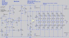
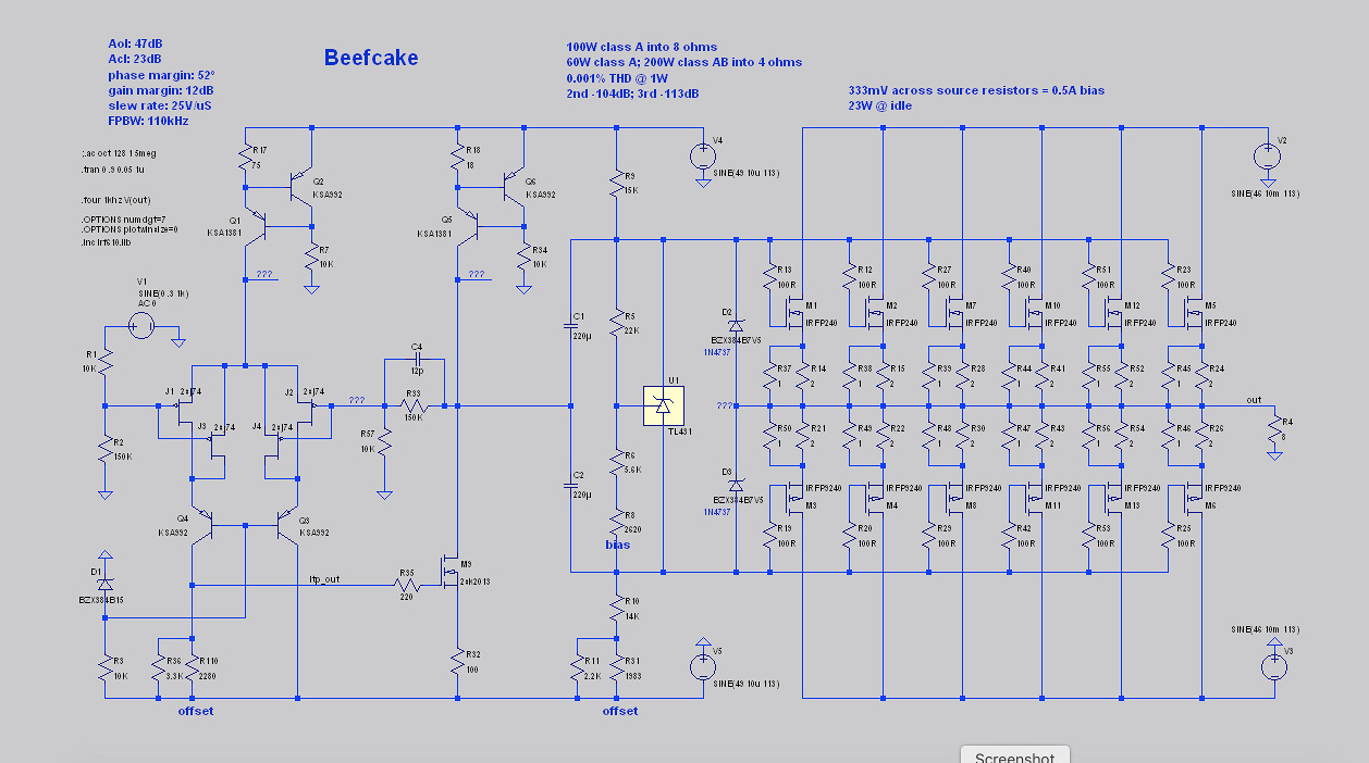
I've been working on something to drive my Maggies. It's essentially a BA-2 beefed up to dump 60 clean watts (and a couple hundred dirty ones) into 4 ohms.
The LTP's CCS uses BJTs to handle the higher rail voltage. They're a bit noisier than a JFET CCS, so the LTP is paralleled a la the J2 in an attempt to claw some of that back. The LTP is also cascoded for the higher rail voltage.
The VAS bootstrap CCS is also replaced with a BJT version. No particular reason, it just looks more symmetrical that way. 😉
The power supply is split with a 49V shunt reg for the front-end and a 46V CRC for the output stage.
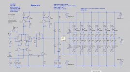
Schematics in the PDFs; a somewhat simplified LTSpice one is also attached.
The LTP's CCS uses BJTs to handle the higher rail voltage. They're a bit noisier than a JFET CCS, so the LTP is paralleled a la the J2 in an attempt to claw some of that back. The LTP is also cascoded for the higher rail voltage.
The VAS bootstrap CCS is also replaced with a BJT version. No particular reason, it just looks more symmetrical that way. 😉
The power supply is split with a 49V shunt reg for the front-end and a 46V CRC for the output stage.
Schematics in the PDFs; a somewhat simplified LTSpice one is also attached.
Attachments
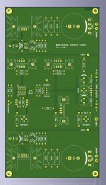
Draft of PCBs. Dissipation is on the order 350W/channel, so a monoblock design is used.
The first board contains a front end with + and - shunt regs; the second is one-half of an output stage. The OS board has output connections at each end so a single design can be used on both sides of the case.
The first board contains a front end with + and - shunt regs; the second is one-half of an output stage. The OS board has output connections at each end so a single design can be used on both sides of the case.
Attachments
I'm reading the F4 Beast thread again, I'm thinking of swaping my BA2 O/P for pucks  - my Apogee Stage are 3 ohm
- my Apogee Stage are 3 ohm
At 3 ohms you've got a lot more options as you probably don't need more voltage than a stock F4/BA1/2/3. I like the idea of a puck-ed BA2.
That CCS has too many parts. 😉
That CCS has too many parts. 😉
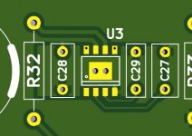
I found a more suitable opamp for the FE shunt regulator (LTC6090). It does require soldering a thermal pad on the bottom to the board. 😎
I put a pair of large vias in the pad to flow some solder through. The datasheet recommends 7 smaller vias, but I think the larger ones will allow me to use the solder as a heat-wick and therefore (hopefully) avoid the whole toaster-oven-reflow thing.
In service the solder filling should more than compensate for the reduce via wall surface.
Attachments
Oh, and I also dropped to a lower voltage Zener for less noise. There's no bypass cap in the Spice sim (because Spice doesn't appear to model Zener noise anyway), but there is in the Kicad schematic and board file.
I've attached the Spice sim of the shunt reg. If anyone wants the Spice sims of the rest just holler.
I've attached the Spice sim of the shunt reg. If anyone wants the Spice sims of the rest just holler.
Attachments
Watching this thread intently. I’ve been planning a BA-2 Turbo for several years and have most of what I need gathered. This is inspiring me to get back on this project.
Cheers,
Terry
Cheers,
Terry

I noticed that after posting, doesn't matter, you'd have to know where abouts I am in the country to use it 😀
Swap the current limmiting resistors for a cc, it will probably sim better, I know it will perform better 😉
The ones in the shunt regulator? I was under the impression that I was already well beyond overkill. (It sims with 4uV ripple from the power supply, and 12uV ripple with a variable load. 100X those amounts would still be fine, no?)
Just started learning the basics of spice, got a long way to go. The numbers look good.
My bench tests with a dynamic load suggest cc; listening is another matter, sometimes I find with some circuits, a simple CRC best, you never know what is until you try all the combinations; thats where the bench and spice go out of the window.
My bench tests with a dynamic load suggest cc; listening is another matter, sometimes I find with some circuits, a simple CRC best, you never know what is until you try all the combinations; thats where the bench and spice go out of the window.
Just started learning the basics of spice, got a long way to go....
Someone else pointed me to this video (while I normally hate videos, this one shows how to determine open-loop gain and stability margins in Spice):
YouTube

Having completed my J2 (and determined that I do indeed like its sound signature), I've started to take a look at Beefcake again.
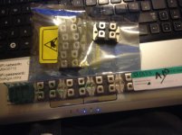
I matched a tube of Harris 240s and a tube of Harris 9240s, and it's easy enough to get close matches so I dropped the source resistors by 33% and marginally increased the bias.
I also swapped out the IRFP610 (in the VAS) for a 2SK2013, which is much more linear.
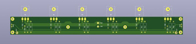
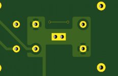
I've selected a pair of 120VA 2x46V transformers for the front ends and a pair of 1500VA 2x35V for the output stages. The output stage transformers have some pretty beefy wire coming out, so I've also done a small variation on the double-bridge board with larger holes and a bit more copper:
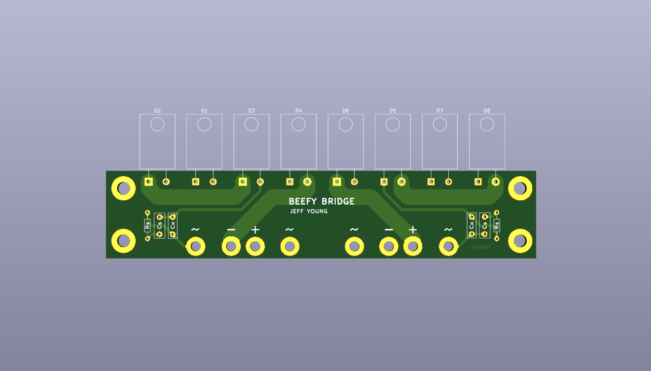
I did not update the PSU board because I'm planning on point-to-point wiring the cap bank.
Cheers,
Jeff.
I matched a tube of Harris 240s and a tube of Harris 9240s, and it's easy enough to get close matches so I dropped the source resistors by 33% and marginally increased the bias.
I also swapped out the IRFP610 (in the VAS) for a 2SK2013, which is much more linear.
I've selected a pair of 120VA 2x46V transformers for the front ends and a pair of 1500VA 2x35V for the output stages. The output stage transformers have some pretty beefy wire coming out, so I've also done a small variation on the double-bridge board with larger holes and a bit more copper:
I did not update the PSU board because I'm planning on point-to-point wiring the cap bank.
Cheers,
Jeff.
Attachments

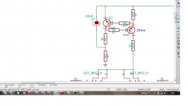
I discovered that the relatively large resistance in the LTP leg led to asymmetrical clipping. The easiest solution would be to raise the FE voltage... only I already have the transformers in hand.
I was able to lower the resistance and symmetricalize (new word, there) the clipping by going from a 1:4 LPT:VAS current ratio to a 1:3 (9mA:36mA -> 10mA:30mA).
The slight bump in LTP current also raised the gain slightly, allowing me to apply a bit more NFB to improve the HF response. (The simulated square-wave output is now, well, more square.)
Some of the annotations on the previous SPICE circuit were stale. They should have been:
FR-3dB: DC - 110kHz
Full-power bandwidth: 75kHz
Slew rate: 18V/uSec
AOL: 43dB
ACL: 22dB
Stability margins: 52º, 12dB
The new numbers are:
FR-3dB: DC - 130kHz
Full-power bandwidth: 85kHz
Slew rate: 20V/uSec
AOL: 44dB
ACL: 21dB
Stability margins: 50º, 13dB
Cheers,
Jeff.
> the relatively large resistance in the LTP leg led to asymmetrical clipping.
And higher even-order THD at all levels.
A current-mirror is an elegant and correct fix. Too expensive in 1969 but this plan dies not seem to be shy of parts; another 2 Q seems minor.
And higher even-order THD at all levels.
A current-mirror is an elegant and correct fix. Too expensive in 1969 but this plan dies not seem to be shy of parts; another 2 Q seems minor.
- Home
- Amplifiers
- Pass Labs
- Beefcake: a beefed-up BA-2