Interesting. It has a pervasive effect:
1) drops distortion by 1/2 (THD @ 1W from .001 -> .00045, so somewhat academic)
2) drops H2 a bit more than H3 (spread between the two has dropped from 9db to 7db)
3) vastly increases the phase margin (50º -> 80º)
4) but introduces a response spike around 5MHz which wipes out the gain margin
5) oddly FPBW is down a bit (to 50kHz) even though SR is up (to 26V/uSec)?
I've added an input filter (10K / 120p) to address the instability. It gives me a 10dB gain margin but with a significant loss in frequency response (-3dB 130kHz -> 75kHz, so again somewhat academic?).
Cheers,
Jeff.
Attachments
Hi, Jeff.
I was wondering if you have a screenshot of the full schematic with the current mirror that you could post. I am curious how the current mirror affects the open loop gain.
My understanding is that switching to an active load will greatly increase the open loop gain, which increases the amount of negative feedback, all other things being kept equal (I'm not an expert on this, so my understanding could be off).
I remember coming across a thread from years ago where someone greatly "improved" an Aleph by adding a current mirror, and the response from NP was along the lines of "yeah, I tried that, but I didn't like the sound as much".
The authors I'm familiar with (Cordell, Self, Sloan) seem to treat the addition of a current mirror as a no-brainer in this situation, so I've always been curious about the topic.
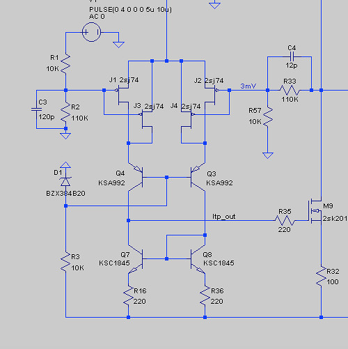
Hi Rory,
I've attached the updated LTSpice file and another one (NOT YET updated with the current mirror) that I use to calculate the OL gain.
I've also attached a JPG in case you don't use LTSpice.
Cheers,
Jeff.
I've attached the updated LTSpice file and another one (NOT YET updated with the current mirror) that I use to calculate the OL gain.
I've also attached a JPG in case you don't use LTSpice.
Cheers,
Jeff.
Attachments
Ha! Yeah, open-loop gain shot up to 110dB. 😱
Since the FB divider only controls closed-loop gain the net result was adding a boat-load of NFB. (Which I suppose explains why the effects were so pervasive.)
I tried limiting open-loop gain by increasing the resistance in the current mirrors, but it was very finicky (illustrating at least that I'm at the boundary of my knowledge).
> I'm at the boundary of my knowledge
I strongly suggest you buy the Douglas Self and Bob Cordell books on amplifier design and take them to bed for a month.
Both have taught self-balancing diff-inputs for many years, and explain how this choice cascades through the design.
Sure you can plow your own path through the jungle, but sometimes you get farther following a map by folks who have been there before.
Oh, indeed I've spent many months with Bob Cordell (and Morgan Jones). But even if I understand it when reading, it doesn't seem to get to long-term memory till I try to make it work. And then I have to go back and read again....
Not that I'm complaining. I'm a long way from where I started, and it's still fun.
Not that I'm complaining. I'm a long way from where I started, and it's still fun.
It's your hobby. Do what you want.
While he was not the first to notice input pair unbalance effect on THD, Sir Self wrote it up very extensively.
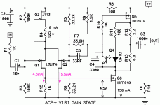
And it's YOUR design. Even Famous Designers break good form. Here is a very recent design from a VERY experienced designer and, if we believe the notes, the input pair is NOT balanced! Certainly no attempt to self-correct balance. The "approximate balance" is set by Q3+R4 against 1k and Vgs of Q6. Unless all the Q3 and Q6 come from the same lot (and they might be, in the first batch) then balance will be not-as-good as Self teaches us.
We must note that JFETs are "softer" so the off-center rise of THD won't be as sharp as Self's BJTs. And this Unnamed Designer has a history of designing to entertain the user rather than technical perfection, and here he *aimed* for non-zero 2nd harmonic.
While he was not the first to notice input pair unbalance effect on THD, Sir Self wrote it up very extensively.
And it's YOUR design. Even Famous Designers break good form. Here is a very recent design from a VERY experienced designer and, if we believe the notes, the input pair is NOT balanced! Certainly no attempt to self-correct balance. The "approximate balance" is set by Q3+R4 against 1k and Vgs of Q6. Unless all the Q3 and Q6 come from the same lot (and they might be, in the first batch) then balance will be not-as-good as Self teaches us.
We must note that JFETs are "softer" so the off-center rise of THD won't be as sharp as Self's BJTs. And this Unnamed Designer has a history of designing to entertain the user rather than technical perfection, and here he *aimed* for non-zero 2nd harmonic.
Attachments
Last edited:
Paul, I hope you are aware that negative phase 2nd harmonic will cancel some of dynamic driver distortion producing cleaner acoustic output.... here he *aimed* for non-zero 2nd harmonic.
Last edited:
And of course there's the venerable Naim NAP250, with a 1K:22K imbalance. People are still arguing why Julian Vereker made that choice (or even if he knew himself)....
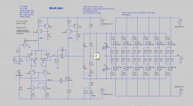
BTW, the Beefcake project ended up getting subsumed into Jam Jar. (Jam Jar includes the Beefcake singled-ended front-end, a CFA push-pull front-end, a Hitachi-topology double-differential push-pull front-end, the Beefcake vertical output stage, and a lateral output stage.)
JamJar: an HPA-1-inspired power amp
The Beefcake front-end also got discrete regulators:

JamJar: an HPA-1-inspired power amp
The Beefcake front-end also got discrete regulators:
Attachments
- Home
- Amplifiers
- Pass Labs
- Beefcake: a beefed-up BA-2