Hello everyone, I've not been posting much on here (Normally I'm on PFM).
I have a Bedini amp that I'd like to bring back into service. Previously it had high DC offset so I have repalced the Lytic caps and the small 0.1uF cap in the feedback circuit.
The problem is that the DC offset is still too high on the left channel. The right measures 0.5mv when warm, but the left is up at 7 to 800mv.
I have checked everything and I can't find anything obviously wrong with it.
the PFM thread is here:
Testing Power transistors in circuit? - pink fish media
A similar circuit diagram is a Bedini 25/25, which is here:
https://dl.dropboxusercontent.com/u/55167127/25_25.JPG
It has a high voltage across R21& R22 on the faulty side, but everything else is normal. I've measured these resistors and they are fine. All the transistors appear fine too. My thinking is that the transistor pairs are not balanced, or something else is amiss and I haven't spotted it
Please help 🙂
You say have a 'high' DC voltage across R22 ? That is not possible unless the reading is in fact caused by instability... which needs a quick scope check really. The voltage across R22 must be 0.00000 volts dc under no signal conditions.
OK 🙂
Well the obvious thing to try which is 5 minutes work and will prove what is going on is just to swap the four input devices between channels. Retain the original positions of each in relation to the diagram.
A similar problem some while ago was here,
http://www.diyaudio.com/forums/soli...nce-rotel-rb-990bx-power-amp.html#post3201530
Spot on Mooly. Swapped all 4 from each side and I now have 800mv on the previously good side and 70 on the bad side. Now I just need to work out which one is dodgy.
Is this just a case of them not being matched? I was told previously that this didn't matter due to the low gain of this amp's 1st stage
Do I have to use exact replacements? ie MPS8099 and 8599, or can I use BC337/327s?
I ask this as I know that there are a lot of people matching these up for the Parsadise phonostage
massive thanks
Dan 🙂
🙂 Lol, your welcome.
No, you can use different devices but the BC's are a bit under rated voltage wise. 45 volts vs 80 volt for the originals. MPSA06 and MPSA56 maybe, or the old favourite of 2N5551 and 2N5401. And if anyone knows any more modern easily available ones then please say so 🙂
I must admit the offset you have is large and yet I somehow doubt one of the originals will be faulty as such... although it would be fascinating to test them extensively and see.
I think you just have to replace them and see how it pans out. Order say 4 of each and then you have a chance of mixing and matching.
I've been looking at the feedback circuit on this one...
It uses a 1000uF 25Volt Lytic cap and a 0.1uF Mullard Tropical Fish. I've replaced the Trop Fish with a Russian Silver Mica, but I'm wondering why I need the 1000uF Lytic?
Why is the value so big? Can I get away with a 100uF (or so) Wet Tant?
thanks for your help
It uses a 1000uF 25Volt Lytic cap and a 0.1uF Mullard Tropical Fish. I've replaced the Trop Fish with a Russian Silver Mica, but I'm wondering why I need the 1000uF Lytic?
Why is the value so big? Can I get away with a 100uF (or so) Wet Tant?
thanks for your help
And is the resistor in series with it 680 ohm ? T
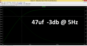
The cap value and resistor are what set the low frequency roll off point of the amp. If you make the cap smaller then the point where the response is -3db down will rise.
The cap value and resistor are what set the low frequency roll off point of the amp. If you make the cap smaller then the point where the response is -3db down will rise.
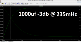
Yes, but make sure the resistor in series with it really is 680 ohm, otherwise the results will be different.
Hi Dan K and Mooly,
Dan K have you had any luck with getting the Bedini properly operational again? I had to redo my amp (25.25) some years ago and I replaced the MPSAs with BC550 & BC560 and the power transistors with MJ802s; the 802s made a heck of a difference. I have also had to replace the 47uF feedback cap twice now on the left channel as it had gone soft (gain on the channel went up.) I also ended up replacing the PSU caps as they both had gone soft by about 20%. Put in slightly larger ones.
Kevin
Gentlemen, I'm afraid I have another Bedini amp problem. This time it's a 25/25 that has a 100Hz hum. I have tried everything that I can think of and I'm stumped.
I've tried the following with no progress:
1. Reverse traffo secondary wires
2. Try other amp module, hum gone (some hiss)
3. Try cap/resistor ground lift (high DC offset)
4. Bias transistor swapping
5. Zen diode swap
6. Power switch bypass
7. Swap disk caps
8. Output & bias devices de solder/ swap
I have another 25/25 to compare and swap amp modules if needed and both have low DC offset and are properly biased. The one with the hum is an earlier model with green circuit boards.
Any suggestions? The circuit diagram is further up thread
Massive thanks
Dan
100Hz 'hum' (it should be more of a buzz with a harsher edge) suggests problems of rectified 50Hz AC getting into the signal chain.
An amp by itself fed off clean DC can not do this in any way, so the problem is either:
1/ Ripple on the rails. This needs a scope to check, possible causes failing reservoir caps.
2/ Poor implementation of the grounding scheme whereby a signal related part of the circuit is returned to a 'dirty' ground.
The above assumes it really is a 'spiky' 100Hz buzz you are hearing.
Thanks Mooly. I should have said that I've renewed the rectifier and the PSU caps. There is nothing wrong with the power supply. I can swap the amp module from one 25/25 to the other and the fault transfers across. It's also definitely 100Hz
OK.
100Hz is tied to the 50Hz mains. It can't come from anywhere else. When you rectify the 50Hz AC voltage from the transformer you get 100Hz ripple as the bridge rectifier converts the AC to a pulsed 100Hz. The diagram below shows this.
If the fault transfers across when swapping a module, then it suggests that something in the physical layout and the way the components are connected is different.
If you examine the modules carefully and look at the routing and layout of the board then there has to be a difference somewhere, or, there is a faulty component such as a failed cap that is making the amplifier susceptible to reproducing the ripple on the rails.
Attachments

- Home
- Amplifiers
- Solid State
- Bedini 100/100 (802mod) high DC offset problem