Does it read 0.0024% THD at 1W without any NFB?
Not only that, it also reads 0.02% at 20W if my eyes don't desert me. This is examplary performance with no fb. I don't know how Nelson comes up with these schemes, but he picks winner after winner. My virtual hat goes off for him.
jd
This thing is realy fascinating for me.
But there shurely is a huge problem, how can i build this by myself?
Mr. Pass you realy know what patience and endurance are, do you?🙂🙂🙂
But there shurely is a huge problem, how can i build this by myself?
Mr. Pass you realy know what patience and endurance are, do you?🙂🙂🙂
It's the parts. 🙂
So far I only have the one, as it takes about 12 hours
to stuff it up, and I have 3 more to go.
Of course I still have to build a front end for it, so we'll see
what the final result might be.
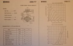
If you want to think really tweaky, here's the 8 ohm
curve on a pair of car batteries:
So far I only have the one, as it takes about 12 hours
to stuff it up, and I have 3 more to go.
Of course I still have to build a front end for it, so we'll see
what the final result might be.
If you want to think really tweaky, here's the 8 ohm
curve on a pair of car batteries:
Attachments

As a follow DIYer, I'll be more interested if it will be a similiar project using thousands of N-jfet in single-ended setup.
Even if it take twice the number of Jfets to get the same output power and the THD is slightly higher.
Of course N-jfet has much lower capacitance, so for a set amount of output power, SE setup might actually have lower capacitance load for the front-end.
Unless the LSJ74 is released, then it will be a different story.
As a follow DIYer, I'll be more interested if it will be a similiar project using thousands of N-jfet in single-ended setup.
Even if it take twice the number of Jfets to get the same output power and the THD is slightly higher.
Of course N-jfet has much lower capacitance, so for a set amount of output power, SE setup might actually have lower capacitance load for the front-end.
Unless the LSJ74 is released, then it will be a different story.
I need 3 weeks to find 2 pcs sj74 in my local (indonesia) market, N Jfet is far far easier
Last edited:
It's the parts. 🙂
So far I only have the one, as it takes about 12 hours
to stuff it up, and I have 3 more to go.
Of course I still have to build a front end for it, so we'll see
what the final result might be.
If you want to think really tweaky, here's the 8 ohm
curve on a pair of car batteries:
Ohh, starting to sound like my paralell LU1014s in B1 configuration... Like Mosnter B1??? But as John Curl might like to read, lower Rg!!!
Last edited:
Papa are we going to see this in BA09? It would be a big attraction.
I start to see a big jfet group by now... 1000 pcs per person, and we will get a better rate if we reach a 100K lot 😀
I start to see a big jfet group by now... 1000 pcs per person, and we will get a better rate if we reach a 100K lot 😀
BTW, I have a batch of Sony 2SK82 and 2SJ28's coming in.
Does anyone know the pinouts on them?
🙂
Does anyone know the pinouts on them?
🙂
BTW, I have a batch of Sony 2SK82 and 2SJ28's coming in.
Does anyone know the pinouts on them?
🙂
if nothing else .....
edit:
http://circuitdiy.mybisi.com/product/53830/2SK82-Sony-P-CH-VFET-for-TA-N88-Class-D-AMP_241978.html
Attachments
Last edited:
JFET for headphones
You could possibly get away parallelling fewer small signal JFETs for a nice headphone amplifier. Because that first W then would be first mW, and the impedance in many cases 600 Ohms. But that might have been done already(?).
RK
PS. Maybe we all should stop posting. Nelson needs all his time to hand solder all these JFETs . The faster he gets it done, the faster we will hear about the result.
You could possibly get away parallelling fewer small signal JFETs for a nice headphone amplifier. Because that first W then would be first mW, and the impedance in many cases 600 Ohms. But that might have been done already(?).
RK
PS. Maybe we all should stop posting. Nelson needs all his time to hand solder all these JFETs
. The faster he gets it done, the faster we will hear about the result.R-K Rønningstad;1916291 said:You could possibly get away parallelling fewer small signal JFETs for a nice headphone amplifier. But that might have been done already(?).
For instance the P-amp with a 10-device Fairchild J271 JFET single ended output stage, published by Mr Rollins earlier this year.
Or build the Mini-Monster with a thousand and one JFETs by parallelling even more small signal JFETs for a nice 50W power amp.
The complementary types J103/K246 both handle 50V, have much lower capacitances, and are both active production items.
Easier to get and much cheaper, especially compared to the current going rate of the J74.
The transconductance of the J103/K246 is too low compared to k170/j74

R-K Rønningstad;1916291 said:You could possibly get away parallelling fewer small signal JFETs for a nice headphone amplifier. Because that first W then would be first mW, and the impedance in many cases 600 Ohms. But that might have been done already(?).
PS. Maybe we all should stop posting. Nelson needs all his time to hand solder all these JFETs
Second point first: Nelson really needed to buy a pick & place machine and a wave solder line anyway.

First point: I did something cruder that that a dozen years ago for a headphone amp to replace the one in my 1988-vintage CD player. The new design was a TL072 followed by a 2N3904 emitter follower with about 300 ohms Re, and the feedback loop taken from the emitter-resistor point. The +- 5V supply in the CD player meant the transistor was passing about 16 milliAmps, with a base current (guessing here) at about 100 microAmps. The darn thing worked surprisingly well, with better bass and inner detail than the previous, somewhat gross, 4556 headphone driver.
Some notes:
1) There were no oscillations to be found, which was my main worry when jamming a cheap transistor inside an opamp feedback loop.
2) Some folks advocate running opamps in simulated class-A mode by running a resistor between the output and -Vcc. This circuit also runs the opamp in class-A, albeit at reduced output current, because the NPN needs continual base current if it's not to cut off.
3) The output impedance is absurdly low because the negative feedback around the opamp reduces the already minimal output Z of the emitter follower.
4) There is a definite current limitation on the output associated with the 300 ohm output resistor. If your load is 300 ohms, then you can expect to see only half the negative rail on the output swing, whereas the positive swing is +Vcc. Voltage division and all that. This isn't an issue with most headphones, since you'll be deaf before hitting the circuit's limits.
SPECULATION ALERT: I suspect the greater sense of ease may, may, have to do with requiring less current from the opamp and thus running into fewer class-AB thermal effects, while the output transistor is running class-A and thus has no signal-varying thermal effects
For instance the P-amp with a 10-device Fairchild J271 JFET single ended output stage, published by Mr Rollins earlier this year.
Whereabout is that amp located? In the grey-area of diyaudio? 😀
- Status
- Not open for further replies.
- Home
- Amplifiers
- Pass Labs
- Beast with a Thousand JFETs