The usual problem with TO-3 casings is also their connection. Usually the collector (I also have emitter types here) is connected via a screw. This is usually not copper. Then there are washers, nuts, sometimes connection via both, two screws...-) I think there are many disadvantages here.I'm out...
And I think: You should stay in, here's a lot to learn about current, signal... audio;-)
Slowly but surely, this thread is (also) losing its entertainment value.
🙁
#
BD139 and BD140 are very fine and ideally suited for LF amplifier circuits.
Nothing more can be said, unless there is a specific application, a dimensioning, a basic circuit ... and so on.
HBt.
🙁
#
BD139 and BD140 are very fine and ideally suited for LF amplifier circuits.
Nothing more can be said, unless there is a specific application, a dimensioning, a basic circuit ... and so on.
HBt.

You just have to ensure your other bits, especially the Mains Cables are also Hand Carved from Unobtainium & Solid BS by Virgins.
We’re doomed! (In C-3PO’s voice).
Somebody mentioned “cables”. Even in jest, the result is the same. It’s good that the BD139/140 dilemma has been resolved to @chalky’s satisfaction already.
BD139 and BD140 are very fine and ideally suited for LF amplifier circuits.
Nothing more can be said, unless there is a specific application, a dimensioning, a basic circuit ... and so on.
HBt.
At the time they saved the day as these were almost the only cheap real drivers, moreover due to the fact
that the Philips were the most widespread.
There were other transistors that were good but often not as readily available as the BDs, from memory these were
the 80-100V BD527-529/528-530 as well as Motorola s MPSU05-07/55-57 and for +-30V amps the excellent BC141/161,
that was about the only good transistors available at the time and all are still up to current standards.
As for LF the Philips BD139 was actualy good enough in 25-30MHz transceivers to drive the final power transistor
for HF powers in the 4-10W range as it could output about 0.5-0.7W HF power.
What is the sonic difference between these two pairs in your HA-5000?Thanks for all of the input. Didn't realise that even modern BD139/BD140 are pretty decent devices. Will definitely use them in preference to the MJE243G/MJE253G
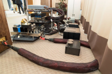
By the way - regarding TO-3: I recommend attaching them in roughly this way to take power and signal into account to some extent - the difference is clearly audible:
Attachments
![DSCN0611[1].JPG](/community/data/attachments/1278/1278434-999f5e9bfb0f55422806912cd89526c4.jpg?hash=SYxFlhyQPn)
There were other transistors that were good but often not as readily available as the BDs, from memory these were
the 80-100V BD527-529/528-530 as well as Motorola s MPSU05-07/55-57 and for +-30V amps the excellent BC141/161,
that was about the only good transistors available at the time and all are still up to current standards.
Funny you should mention the now unobtainium but highly desirable at the time MPSU05 family. Same part as the MPSA05 on a little bigger leadfame so it can cool better than a TO-92. Excellent transistors overall, and they don’t take any secret sauce to make well. Recall the BD139 had a TO-92 equivalent, too. None of them are especially big, or hard to clone with any modern silicon fab line.
BC 639BD139 had a TO-92 equivalent, too
In fact, the TO-92 or TO-92L would be a better choice when it comes to audio. My experience is that the most are superior to the TO-126 in terms of sound. This circuit and its task should work well with it.
There are some TO-92s that I do not recommend at this time. I have tested a few batches over a few years: no 2N types and no MPSA either. The SA - SD all sounded in the upper middle range.
Here, too, you have to decide: audio unsuitable transistor, e.g. BD139 in TO-126 housing with "ideal" current, which does not improve its sound, or audio suitable transistor with lower current, which does not worsen its sound;-) The ear is picky and merciful at the same time - just audio engineering;-)

Funny you should mention the now unobtainium but highly desirable at the time MPSU05 family. Same part as the MPSA05 on a little bigger leadfame so it can cool better than a TO-92. Excellent transistors overall, and they don’t take any secret sauce to make well. Recall the BD139 had a TO-92 equivalent, too. None of them are especially big, or hard to clone with any modern silicon fab line.
Even more funny is that like the BD139 the MSPUs could also be used as RF drivers up to 30MHz, as far as we re
talking audio it s a mystery for me that such good devices were obsoleted to be often replaced by parts that were
no better or not replaced at all, even in a financial perspective it made absolutely no sense.
As for the BC639/640 they are not exactly BD139/140, they are actualy better as VAS, i suspect that they are 80V
versions of the BC141/161 wich were precisely way better than the BDs for this stage.
DBLTs are no guarantee of "scientificity". Use them if you want to proof a method if it does not provide clear results.Presumably, you have tested this proposition (like I have 😊 ) in DBLTs
Seeing DBLTs as fundamentally scientific, and relying on it, can lead to the development of unsuitable methods. For example, switching back and forth without pause between audio devices to be compared is an unsuitable method: hearing is an swinging in and out process that involves the entire organism. It makes sense to allow the organism to decay, to fade out. At least 10 seconds pause I recommend;-)
You obviously haven't taken part in any DBLTs where the switching might be over several hours. It just takes more time and $$$ to organise as each subject MUST be tested alone.For example, switching back and forth without pause between audio devices to be compared is an unsuitable method: hearing is an swinging in and out process that involves the entire organism. It makes sense to allow the organism to decay, to fade out. At least 10 seconds pause I recommend;-)
That's why its important to quickly weed out da deaf wannabe Golden Pinnae (those giving random results in DBLTs) . After 2 decades of conducting DBLTs, I'll put serious $$$ that the ones who hear differences between mains cables, connectors, bla bla ...... are deaf. 😊 Surprise SURPRISE !!
One basis for DBLTs in audio is the deliberate, argued, audio meaningful set up of speakers. I recommend:
Move the speakers together once to zero distance. Listen. Move them 10 cm apart, listen. Move them further apart, listen. And keep doing this until the sound image tears apart. Then move them together again until they play together: most "stereo signals" are mono (present on both channels). Since loudspeakers have different imaging sizes and shapes, you can determine the optimum set-up in this way. It will be that your biggest speakers will be less than 1,5 meter apart (center-center), so that width, depth, height, coherence, contour, colors... interact and become "round".
Note the angle and distance to the rear wall too.
You will be able to use this arrangement as a tool because, for example, individual parts also have different image sizes. Correcting the speaker position when changing in order to get a coherent image shape in size, width, depth and height makes a supposed difference physically perceptible;-)
Perhaps you have a PP amplifier with a BD139 bias control. Replace it with a, as example, BD441. And just listen. At some point you can tell us after how many DBLTs you have decided which of these BDs you want to take to the island;-)
You too are not deaf;-)
Even more funny is that like the BD139 the MSPUs could also be used as RF drivers up to 30MHz, as far as we re
talking audio it s a mystery for me that such good devices were obsoleted to be often replaced by parts that were
no better or not replaced at all, even in a financial perspective it made absolutely no sense.
As for the BC639/640 they are not exactly BD139/140, they are actualy better as VAS, i suspect that they are 80V
versions of the BC141/161 wich were precisely way better than the BDs for this stage.
Through-hole assembly is going away. Eventually ST and ON will discontinue the all BD’s in TO-126 altogether. They will continue to put the same dies in SOT223.
The 639/139 from Fairchild are the same innards. Not everybody does that, and probably not the original Philips.
As far as the bias control transistor having a huge impact on the sound, I’ll really eat my hat. I think I’ll have two.
Through-hole assembly is going away. Eventually ST and ON will discontinue the all BD’s in TO-126 altogether. They will continue to put the same dies in SOT223.
The 639/139 from Fairchild are the same innards. Not everybody does that, and probably not the original Philips.
Well, that s infortunate, but there s some hope as i just realised that it s really incredible how much we exgerately focused on semiconductors and circuitries, and that we are eventualy horribly lackluster when it comes to bleeding hedge audio cables technology, there s a whole world left for us to discover with an huge personal progress margin still untapped.
Attachments
One basis for DBLTs in audio is the deliberate, argued, audio meaningful set up of speakers. I recommend:
Move the speakers together once to zero distance. Listen. Move them 10 cm apart, listen. Move them further apart, listen. And keep doing this until the sound image tears apart. Then move them together again until they play together: most "stereo signals" are mono (present on both channels). Since loudspeakers have different imaging sizes and shapes, you can determine the optimum set-up in this way. It will be that your biggest speakers will be less than 1,5 meter apart (center-center), so that width, depth, height, coherence, contour, colors... interact and become "round".
Note the angle and distance to the rear wall too.
You will be able to use this arrangement as a tool because, for example, individual parts also have different image sizes. Correcting the speaker position when changing in order to get a coherent image shape in size, width, depth and height makes a supposed difference physically perceptible;-)
Perhaps you have a PP amplifier with a BD139 bias control. Replace it with a, as example, BD441. And just listen. At some point you can tell us after how many DBLTs you have decided which of these BDs you want to take to the island;-)
You too are not deaf;-)
Hi cumbb
I did'nt find BD441 cob in datasheets. Do you use BD441 and 442 for VAS, bias control and drivers?
Regards
- Status
- Not open for further replies.
- Home
- Amplifiers
- Solid State
- BD139/BD140 dilemma